Pin description pin configuration – Rainbow Electronics MAX8848Z User Manual
Page 7
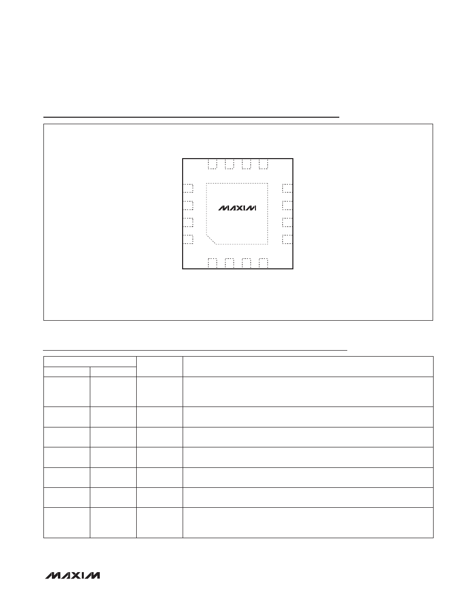
High-Performance Negative Charge Pump
for 7 White LEDs in 3mm x 3mm Thin QFN
MAX8848Y/MAX8848Z
_______________________________________________________________________________________ 7
Pin Description
Pin Configuration
15
16
14
13
6
5
7
GND
C2P
8
IN
LED4
LED2
LED5
1
2
LED7
4
12
11
9
CPWM (ENB)
ENA
EP
( ) FOR MAX8848Y ONLY
LED1
NEG
C1N
C2N
MAX8848Y
MAX8848Z
C1P
LED3
3
10
LED6
THIN QFN
TOP VIEW
+
PIN
NAME
FUNCTION
MAX8848Y
MAX8848Z
1
1
IN
Supply Voltage Input. The input voltage range is 2.7V to 5.5V. Bypass IN to GND
with a 1FF ceramic capacitor as close as possible to the IC. IN is high imped-
ance during shutdown. Connect IN to the anodes of all the LEDs.
2
2
GND
Ground. Connect GND to system ground and the input bypass capacitor as
close as possible to the IC.
3
3
C1P
Transfer Capacitor 1 Positive Connection. Connect a 1FF ceramic capacitor from
C1P to C1N.
4
4
C2P
Transfer Capacitor 2 Positive Connection. Connect a 1FF ceramic capacitor from
C2P to C2N.
5
5
C2N
Transfer Capacitor 2 Negative Connection. Connect a 1FF ceramic capacitor
from C2P to C2N. An internal 10kI resistor pulls C2N to GND during shutdown.
6
6
C1N
Transfer Capacitor 1 Negative Connection. Connect a 1FF ceramic capacitor
from C1P to C1N.
7
7
NEG
Charge-Pump Negative Output. Connect a 1FF ceramic capacitor from NEG to
GND. In shutdown, an internal 10kI resistor pulls NEG to GND. Connect the
exposed pad to NEG directly under the IC.