Applications information – Rainbow Electronics MAX8848Z User Manual
Page 12
High-Performance Negative Charge Pump
for 7 White LEDs in 3mm x 3mm Thin QFN
MAX8848Y/MAX8848Z
12 _____________________________________________________________________________________
Low LED Current Levels
The MAX8848Y internally generates a PWM signal to
obtain higher resolution at lower currents. See the Single-
Wire Serial-Pulse Dimming Response (MAX8848Y) graph
in the Typical Operating Characteristics section. When
the LED current is set below 6.4mA, the IC adjusts not
only LED DC current, but the duty cycle that is controlled
by the PWM signal. The frequency of the PWM dimming
signal is set at 16kHz with a minimum duty cycle of 1/8 to
avoid the LED flickering effect to human eyes and also to
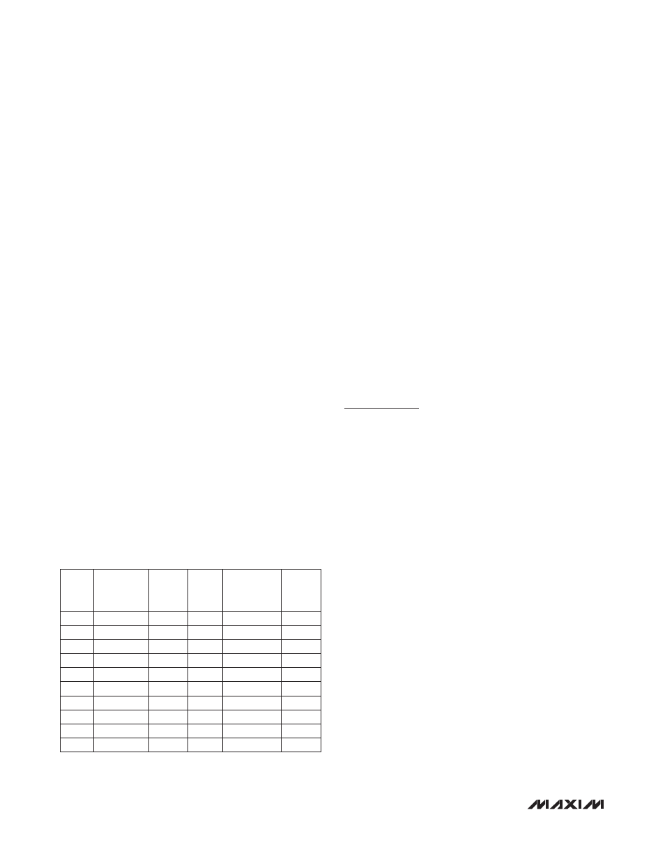
avoid interference in the audio frequency range. Table 3
shows the current level and the corresponding duty cycle.
Shutdown Mode
The MAX8848Y/MAX8848Z are in shutdown mode when
both ENA and ENB are held low for 8ms or longer. In
shutdown, NEG is pulled to GND with a 10k
Ω internal
resistor.
Temperature Derating Function
The MAX8848Y/MAX8848Z contain a derating func-
tion that automatically limits the LED current at high
temperatures in accordance with the recommended
derating curve of popular white LEDs. The derating
function enables the safe usage of higher LED current
at room temperature, thus reducing the number of LEDs
required to backlight the display. The derating circuit
lowers the LED current at approximately 2.5%/°C once
the die temperature is above +60°C. The typical derating
function characteristic is shown in the Typical Operating
Characteristics.
Power-Up LED Short Detection and
Open-Fault Protection
The MAX8848Y/MAX8848Z contain special circuitry to
detect short-circuit conditions at power-up and disable
the corresponding current regulator to avoid wasting
battery current. Connect any unused LED_ to IN to dis-
able the corresponding current regulator. If an LED fails
short-circuit detection after startup, the current regulator
continues the current regulated operation until IC power
is cycled and the short circuit is detected during the
subsequent startup.
An open-circuit LED failure drives the voltage on the cor-
responding LED current regulator output below the swi-
tchover threshold, enabling the negative charge pump.
Thermal Shutdown
The MAX8848Y/MAX8848Z include a thermal-limit circuit
that shuts down the IC above approximately +160°C.
The IC turns on after it cools by approximately 20°C.
Applications Information
Input Ripple
For LED drivers, input ripple is more important than
output ripple. The amount of input ripple depends on
the source supply’s output impedance. Add a lowpass
filter to the input of the MAX8848Y/MAX8848Z to further
reduce input ripple. Alternatively, increasing C
IN
from
1.0µF to 2.2µF (or 4.7µF) cuts input ripple in half (or in
fourth) with only a small increase in footprint.
Capacitor Selection
Ceramic capacitors are recommended due to their small
size, low cost, and low ESR. Select ceramic capacitors
that maintain their capacitance over temperature and DC
bias. Capacitors with X5R or X7R temperature character-
istics generally perform well. Recommended values are
shown in the Typical Operating Circuit. Using a larger
value input capacitor helps to reduce input ripple (see
the Input Ripple section).
PCB Layout and Routing
The MAX8848Y/MAX8848Z are high-frequency switched-
capacitor voltage inverters. For best circuit performance,
use a solid ground plane and place all capacitors as
close as possible to the IC. Use large traces for the
power-supply inputs to minimize losses due to parasitic
trace resistance and to route heat away from the device.
Refer to the MAX8848Z evaluation kit data sheet for an
example PCB layout.
Table 3. Internal PWM Duty Cycle vs. LED
Set Current
*Maximum I
LED
is the full reference current when the internal
PWM signal has 100% duty cycle at the lower level currents.
I
LED
(mA)
MAXIMUM
I
LED
(mA)*
DUTY
CYCLE
(n/8)
I
LED
(mA)
MAXIMUM
I
LED
(mA)*
DUTY
CYCLE
(n/8)
6.4
6.4
8
1.2
1.6
6
5.6
6.4
7
1.0
1.6
5
4.8
6.4
6
0.8
0.8
8
4.0
6.4
5
0.7
0.8
7
3.2
3.2
8
0.6
0.8
6
2.8
3.2
7
0.5
0.8
5
2.4
3.2
6
0.4
0.8
4
2.0
3.2
5
0.3
0.8
3
1.6
1.6
8
0.2
0.8
2
1.4
1.6
7
0.1
0.8
1