Rainbow Electronics MAX15041 User Manual
Page 13
MAX15041
Low-Cost, 3A, 4.5V to 28V Input, 350kHz, PWM
Step-Down DC-DC Regulator with Internal Switches
______________________________________________________________________________________
13
If C
OUT
is large, or exhibits a lossy equivalent series
resistance (large ESR), the circuit’s second zero may
come into play around the crossover frequency (f
CO
=
ω
CO
/2
π). In this case, a third pole may be induced by a
second (optional) small compensation capacitor (C
CC
),
connected from COMP to SGND.
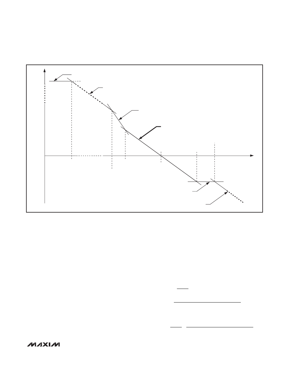
The loop response’s fourth asymptote (in bold, Figure
2) is the one of interest in establishing the desired
crossover frequency (and determining the compensa-
tion component values). A lower crossover frequency
provides for stable closed-loop operation at the
expense of a slower load and line transient response.
Increasing the crossover frequency improves the tran-
sient response at the (potential) cost of system instabili-
ty. A standard rule of thumb sets the crossover
frequency ≤ 1/10 of the switching frequency (for the
MAX15041, this is approximately 35kHz for the 350kHz
fixed switching frequency).
First, select the passive and active power components
that meet the application’s requirements. Then, choose
the small-signal compensation components to achieve
the desired closed-loop frequency response and phase
margin as outlined in the
Closing the Loop: Designing
the Compensation Circuitry
section.
Closing the Loop: Designing the
Compensation Circuitry
1) Select the desired crossover frequency. Choose f
CO
equal to 1/10
th
of f
SW
, or f
CO
≈ 35kHz.
2) Select R
C
using the transfer-loop’s fourth asymptote
gain (assuming f
CO
> f
P1
, f
P2
, and f
Z1
and setting
the overall loop gain to unity) as follows:
therefore:
R
V
V
f
C
ESR R
g
G
C
OUT
FB
CO
OUT
LOAD
MV
MOD
=
Ч
Ч
Ч
Ч
+
(
)
Ч
Ч
2
π
R
R
LOAD
1
1
2
=
Ч
Ч
Ч
Ч
Ч
Ч
Ч
Ч
V
V
g
R
G
R
f
C
ES
FB
OUT
MV
C
MOD
LOAD
CO
OUT
π
R
R R
LOAD
+
(
)
1ST ASYMPTOTE
V
FB
x
V
OUT
-1
x
10
AVEA[dB]/20
x
G
MOD
x
R
LOAD
2ND ASYMPTOTE
V
FB
x
V
OUT
-1
x
g
MV
x
(C
C
)
-1
x
G
MOD
x
R
LOAD
3RD ASYMPTOTE
V
FB
x
V
OUT
-1
x
g
MV
x
(C
C
)
-1
x
G
MOD
x
R
LOAD
x
(C
OUT
(ESR + R
LOAD
))
-1
4TH ASYMPTOTE
V
FB
x V
OUT
-1
x g
MV
x R
C
x G
MOD
x R
LOAD
x (C
OUT
(ESR + R
LOAD
))
-1
5TH ASYMPTOTE
V
FB
x
V
OUT
-1
x
g
MV
x
R
C
x
G
MOD
x
(ESR || R
LOAD
)
6TH ASYMPTOTE
V
FB
x
V
OUT
-1
x
g
MV
x
(C
CC
)
-1
x
G
MOD
x
(ESR || R
LOAD
)
UNITY
GAIN
RAD/S
3RD POLE
(C
CC
R
C
)
-1
2ND ZERO
(C
OUT
ESR)
-1
1ST ZERO
(C
C
R
C
)
-1
2ND POLE
(C
OUT
(ESR + R
LOAD
))
-1
1ST POLE
gmV x (10
AVEA[dB]/20
C
C
)
-1
CO
Figure 2. Asymptotic Loop Response of Peak Current-Mode Regulator