Pin description – Rainbow Electronics MAX5457 User Manual
Page 6
MAX5456/MAX5457
Stereo Audio Taper Potentiometers
with Pushbutton Interface
6
_______________________________________________________________________________________
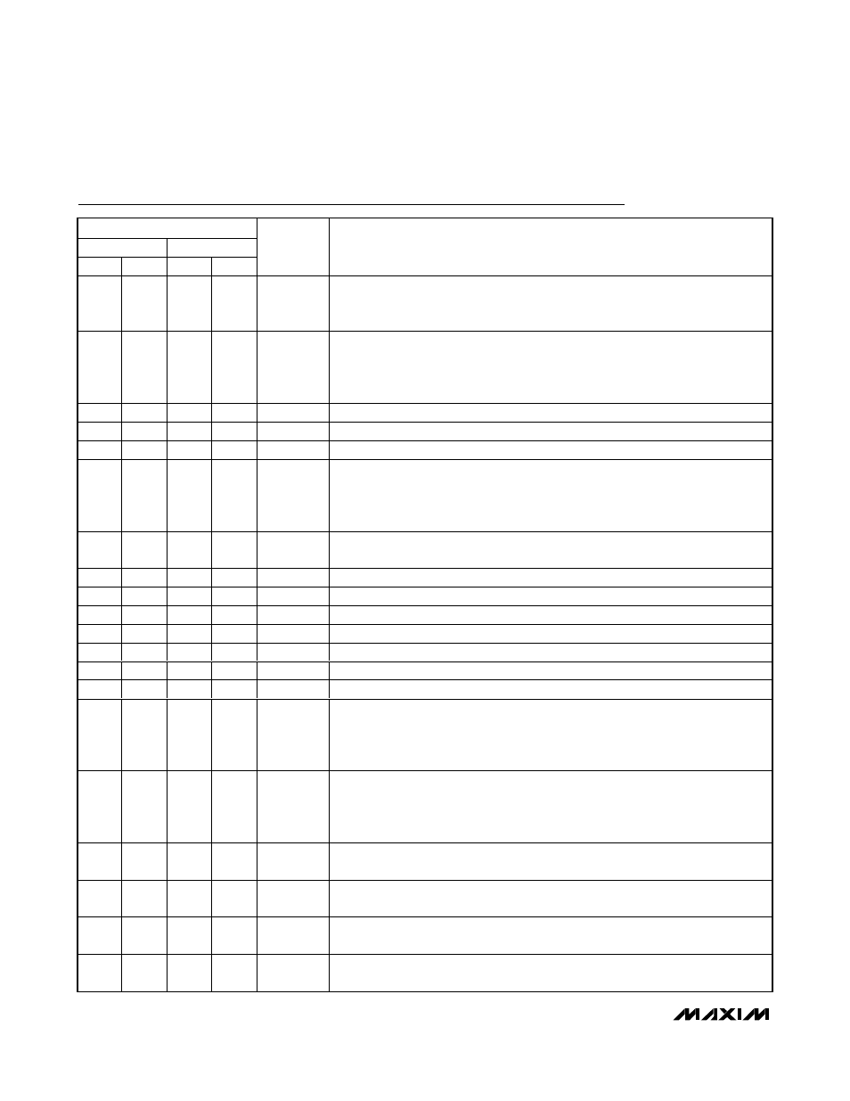
Pin Description
PIN
MAX5457
MAX5456
TQFN
QSOP
TQFN
QSOP
NAME
FUNCTION
1
3
—
—
MODE
Volume/Balance Control. Each transition from high to low toggles between volume
and balance modes.
MODE is pulled high internally with a 50k
Ω resistor to V
LOGIC
.
On power-up, the MAX5457 is in volume-control mode.
2
4
—
—
MODE_IND
Volume-Control/Balance-Control Mode Indicator Open-Drain Output. Connect to
an LED through a resistor to V
LOGIC
. When the LED is on, the MAX5457 is in
balance-control mode. When the LED is off, the MAX5457 is in volume-control
mode. See the Mode Indicator, MODE_IND section for more detail.
3
5
3
5
H0
Potentiometer 0 High Terminal. H0 and L0 terminals can be reversed.
4
6
4
6
L0
Potentiometer 0 Low Terminal. L0 and H0 terminals can be reversed.
5
7
5
7
W0
Potentiometer 0 Wiper Terminal
6
8
6
8
SHDN
Active-Low Shutdown Input. In shutdown mode, the MAX5456/MAX5457 store the
last wiper settings. The wipers move to the L end of the resistor string, and the H
end of the resistor string disconnects from the signal input. Terminating shutdown
mode restores the wipers to their previous settings.
7
9
7
9
MUTE
Mute Input. When
MUTE is low, the wiper goes to the highest attenuation setting
(see Table 1).
MUTE is internally pulled up with 50k
Ω to V
LOGIC
.
8
10
8
10
W1
Potentiometer 1 Wiper Terminal
9
11
9
11
L1
Potentiometer 1 Low Terminal. L1 and H1 terminals can be reversed.
10
12
10
12
H1
Potentiometer 1 High Terminal. H1 and L1 terminals can be reversed.
11
13
11
13
V
SS
Negative Power Supply. Bypass with 0.1µF to ground.
12
14
12
14
GND
Ground
13
15
13
15
V
LOGIC
Digital Logic Power Supply. Bypass with 0.1µF to ground.
14
16
14
16
V
DD
Analog Power Supply. Bypass with 0.1µF to ground.
15
1
—
—
DN/BAL0
Downward Volume/Channel 0 Balance-Control Input. In volume mode, pressing
DN/BAL0 moves both wipers towards the L terminals. In balance mode, pressing
DN/BAL0 moves the balance towards channel 0. DN/BAL0 is internally pulled up
with 50k
Ω to V
LOGIC
.
16
2
—
—
UP/BAL1
Upward Volume/Channel 1 Balance-Control Input. In volume mode, pressing
UP/BAL1 moves both wipers towards the H terminals. In balance mode, pressing
UP/BAL1 moves the balance towards channel 1. UP/BAL1 is internally pulled up
with 50k
Ω to V
LOGIC
.
—
—
1
3
BAL1
Channel 1 Balance-Control Input. Pressing
BAL1 moves the balance towards
channel 1.
BAL1 is internally pulled up with 50k
Ω to V
LOGIC
.
—
—
2
4
BAL0
Channel 0 Balance-Control Input. Pressing
BAL0 moves the balance towards
channel 0.
BAL0 is internally pulled up with 50k
Ω to V
LOGIC
.
—
—
15
1
VOLDN
Downward Volume-Control Input. Pressing
VOLDN moves both wipers towards
the L terminals.
VOLDN is internally pulled up with 50k
Ω to V
LOGIC
.
—
—
16
2
VOLUP
Upward Volume-Control Input. Pressing
VOLUP moves both wipers towards the
H terminals.
VOLUP is internally pulled up with 50k
Ω to V
LOGIC
.