Rainbow Electronics MAX17083 User Manual
Page 2
MAX17083
Low-Voltage, Internal Switch,
Step-Down Regulator
2
_______________________________________________________________________________________
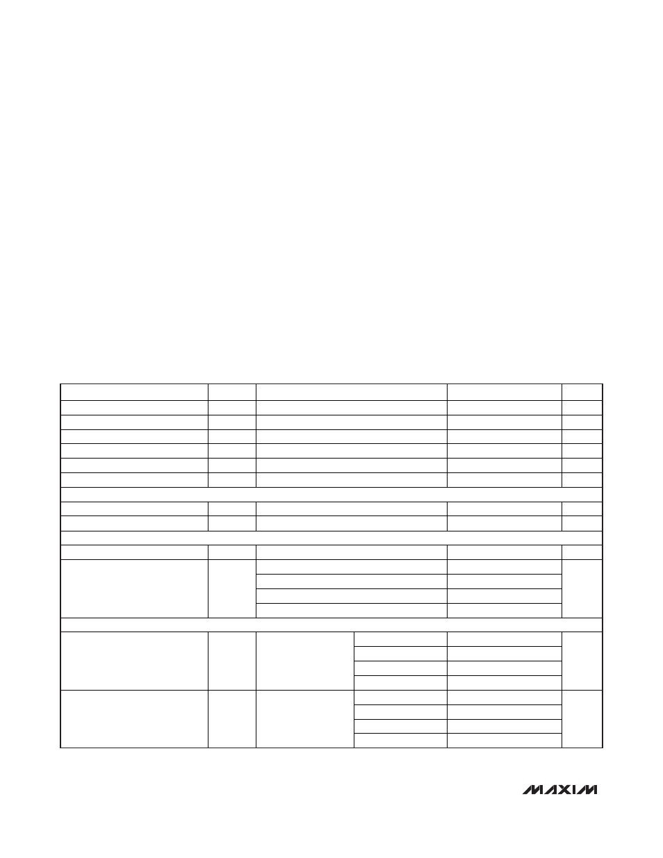
ABSOLUTE MAXIMUM RATINGS
ELECTRICAL CHARACTERISTICS
(Circuit of Figure 1, V
IN
= V
FREQ
= V
CC
= V
EN
= 5V, I
REF
= no load, T
A
= 0°C to +85°C, unless otherwise noted. Typical values are at
T
A
= +25°C.)
Stresses beyond those listed under “Absolute Maximum Ratings” may cause permanent damage to the device. These are stress ratings only, and functional
operation of the device at these or any other conditions beyond those indicated in the operational sections of the specifications is not implied. Exposure to
absolute maximum rating conditions for extended periods may affect device reliability.
IN to PGND...............................................................-0.3V to +6V
V
CC
to GND ..............................................................-0.3V to +6V
EN to GND................................................................-0.3V to +6V
REF, FB, SET, FREQ, POK to GND ............-0.3V to (V
CC
+ 0.3V)
LX to GND (Notes 1, 2) ................................-0.6V to (V
IN
+ 0.3V)
BST to GND.........................................(V
CC
- 0.3V) to (V
LX
+ 6V)
GND to PGND (Note 2) .........................................-0.3V to +0.3V
REF Short-Circuit Current......................................................1mA
Continuous Power Dissipation, Multilayer PCB (T
A
= +70°C)
24-Pin, 4mm x 4mm TQFN
(derate 27.8mW/°C above +70°C) ........................2222mW
Operating Temperature Range ...........................-40°C to +85°C
Junction Temperature ......................................................+150°C
Storage Temperature Range .............................-65°C to +150°C
Lead Temperature (soldering, 10s) .................................+300°C
PARAMETER
SYMBOL
CONDITIONS
MIN
TYP
MAX
UNITS
IN Input Voltage Range
V
IN
2.4
5.5
V
V
CC
Input Voltage Range
V
CC
4.5
5.5
V
IN Undervoltage Threshold
No hysteresis
2.1
2.4
V
Vcc Undervoltage Threshold
Rising edge, 160mV hysteresis
4.2
4.5
V
Shutdown Supply Current
EN = GND, measured at V
CC
, T
A
= +25°C
0.1
1.0
μA
Supply Current
Regulator enabled
65
95
μA
REFERENCE
Reference Output Voltage
V
REF
No
load
1.24 1.25 1.26
V
Reference Load Regulation
-1μA < I
REF
< +50μA
3
10
mV
OSCILLATOR
Oscillator Frequency f
OSC
FREQ = GND
0.45
0.50
0.55
MHz
FREQ = V
CC
1.50
FREQ = open
1.00
FREQ = REF
0.75
FREQ Settings
FREQ = GND
0.50
MHz
INTERNAL 5A STEP-DOWN CONVERTER
SET = GND
0.754
0.765
0.774
SET = REF
1.107
1.122
1.136
SET = open
1.51
1.53
1.55
FB Regulation Voltage
(No Load)
V
FB
No
load
SET = 5V
1.812
1.836
1.86
V
SET = GND
0.72
0.774
SET = REF
1.07
1.136
SET
=
open
1.45 1.55
FB Regulation Voltage
(Full Load)
V
FB
I
OUT
= 4A
SET
=
5V
1.76 1.86
V
Note 1: LX has clamp diodes to PGND and IN. If continuous current is applied through these diodes, thermal limits must be observed.
Note 2: Measurements valid using 20MHz bandwidth limit.