Low-voltage, internal switch, step-down regulator, Smps detailed description – Rainbow Electronics MAX17083 User Manual
Page 10
MAX17083
SMPS Detailed Description
Fixed-Frequency,
Current-Mode PWM Controller
The heart of the current-mode PWM controller is a multi-
stage, open-loop comparator that compares the output
voltage-error signal with respect to the reference volt-
age, the current-sense signal, and the slope compensa-
tion ramp (Figure 2). The MAX17083 uses a direct-
summing configuration, approaching ideal cycle-to-
cycle control over the output voltage without a traditional
error amplifier and the phase shift associated with it.
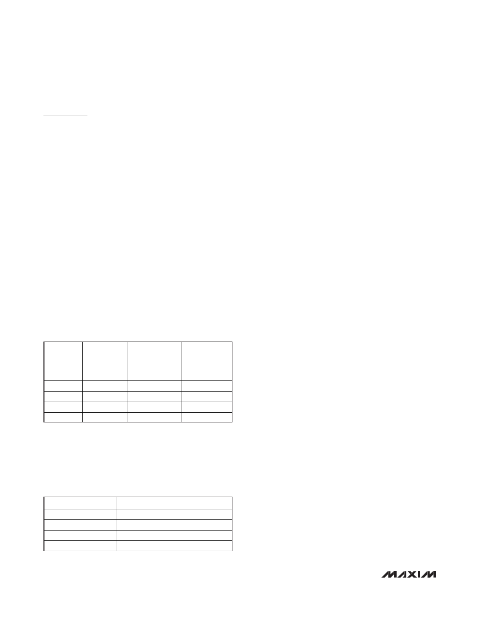
Frequency Selection (FREQ)
The FREQ input selects the PWM mode switching fre-
quency. FREQ is a four-level input to set the regulator
switching frequency. The regulator’s switching frequen-
cy is set according to Table 1, and latched at the
beginning of soft-start. High-frequency (FREQ = V
CC
)
operation optimizes the application for the smallest
component size, trading off efficiency due to higher
switching losses. This might be acceptable in ultra-
portable devices where the load currents are lower.
Low-frequency (FREQ = GND) operation offers the best
overall efficiency at the expense of component size and
board space.
FB Regulation Selection (SET)
The SET input selects one of the four preset feedback
regulation voltage levels. The SET pin is a four-level
input signal to set the FB regulation voltage. The regu-
lator’s feedback regulation voltage is set according to
Table 2, and latched at the beginning of soft-start.
Adjustable Output-Voltage Operation Mode
The MAX17083 produces an adjustable 0.75V to 2.7V
output voltage from the system’s 3.3V or 5V input sup-
ply by using a resistive feedback divider. Set FB to
0.75V (SET = GND) in adjustable mode.
Light-Load Operation
An inherent automatic switchover to pulse-skipping
(PFM operation) takes place at light loads. This
switchover is affected by a comparator that truncates
the low-side switch on-time at the inductor current’s
zero crossing. The zero-crossing comparator senses
the inductor current during the off-time. Once the cur-
rent through the low-side MOSFET drops below 100mA,
the zero-crossing comparator, turns off the low-side
MOSFET. This prevents the inductor from discharging
the output capacitors and forces the switching regula-
tor to skip pulses under light-load conditions to avoid
overcharging the output.
Idle-Mode Current-Sense Threshold
When MAX17083 operates in pulse-skipping mode, the
on-time of the step-down controller terminates when
both the output voltage exceeds the feedback thresh-
old, and the current-sense voltage exceeds the idle-
mode current-sense threshold. Under light-load
conditions, the on-time duration depends solely on the
idle-mode current-sense threshold. This forces the con-
troller to source a minimum amount of power with each
cycle. To avoid overcharging the output, another on-
time cannot be initiated until the output voltage drops
below the feedback threshold. Since the zero-crossing
comparator prevents the switching regulator from sink-
ing current, the MAX17083 switching regulator must
skip pulses. Therefore, the controller regulates the
valley of the output ripple under light-load conditions.
The minimum idle-mode current requirement causes
the threshold between pulse-skipping PFM operation
and constant PWM operation to coincide with the
boundary between continuous and discontinuous
inductor-current operation (also known as the critical
conduction point). The load-current level at which
PFM/PWM crossover occurs (I
LOAD(SKIP)
) is equivalent
to half the idle-mode current threshold (see the
Electrical Characteristics
table for the idle-mode thresh-
old of the regulator). The switching waveforms can
appear noisy and asynchronous at light-load pulse-
skipping operation, but this is a normal operating con-
dition that results in high light-load efficiency.
Trade-offs in PFM noise and light-load efficiency are
made by varying the inductor value. Generally, low
inductor values produce a broader efficiency vs. load
Low-Voltage, Internal Switch,
Step-Down Regulator
10
______________________________________________________________________________________
FREQ PIN
SELECT
SWITCHING
FREQ, f
SW
SOFT-START
TIME (ms)
1833/f
SW
STARTUP
BLANKING
TIME (ms)
3055/f
SW
V
CC
1.5MHz
1.22
2.0
Open 1MHz
1.83
3.1
REF 750kHz
2.44
4.1
GND 500kHz
3.67
6.1
Table 1. MAX17083 FREQ Table
SET PIN SELECT
FB REGULATION VOLTAGE (V)
V
CC
1.8
Open 1.5
REF 1.1
GND 0.75
Table 2. MAX17083 SET Table