C-compatible serial interface in a sot23, Table 1. address selection – Rainbow Electronics MAX6626 User Manual
Page 8
MAX6625/MAX6626
9-Bit/12-Bit Temperature Sensors with
I
2
C-Compatible Serial Interface in a SOT23
8
_______________________________________________________________________________________
Control Registers
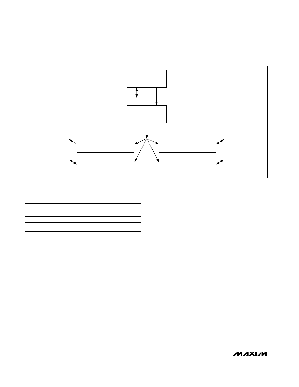
Five registers control the operation of the MAX6625/
MAX6626 (Figure 5 and Tables 2 through 7). The point-
er register should be the first addressed and deter-
mines which of the other four registers will be acted on.
The other four are the temperature, configuration, high-
temperature (T
HIGH
), and low-temperature (T
LOW
) reg-
isters. The temperature register is 9 bits for the
MAX6625 and 12 bits for the MAX6626, read only, and
contains the latest temperature data. The register
length is 16 bits with the unused bits masked to 0. The
digital temperature data contained in the temperature
register is in °C, using a two’s-complement format with
1LSB corresponding to 0.5°C for the MAX6625 and
0.0625°C for the MAX6626 (Table 8).
The configuration register is 8 bits, read/write, and con-
tains the fault queue depth, the temperature alarm
polarity select bit, the interrupt mode select bit, and the
shutdown control bit. The high-temperature register is
9 bits, read/write, and contains the value that triggers
the overtemperature alarm. The low-temperature regis-
ter is 9 bits, read/write, and contains the value to which
the temperature must fall before the overtemperature
alarm is deasserted, if in comparator mode.
Temperature Conversion
An on-chip bandgap reference produces a signal pro-
portional to absolute temperature (PTAT), as well as the
temperature-stable reference voltage necessary for the
analog-to-digital conversion. The PTAT signal is digi-
tized by the on-board ADC to a resolution of 0.5°C for
the MAX6625, and 0.0625°C for the MAX6626. The
resulting digital value is placed in the temperature reg-
ister. The temperature conversion runs continuously
and asynchronously from the I
2
C-compatible interface
at a rate of 133ms per conversion. When the tempera-
ture register is read, the most recently completed con-
version result is provided and the currently active
conversion is aborted. When the bus transaction is fin-
ished by an I
2
C-compatible stop condition conversions
resume.
Overtemperature Alarm
The dedicated overtemperature output pin, OT, has
programmable polarity and two modes: comparator
and interrupt. Polarity and mode are selected through
the configuration register, and alarm activity is gov-
erned by a fault queue. Fault queue depth is also
selected through the configuration register (Tables 5
and 6). The MAX6625P/MAX6626P OT output is open
POINTER REGISTER
(SELECTS REGISTER FOR
COMMUNICATION)
INTERFACE
SDA
SCL
DATA
ADDRESS
REGISTER SELECT
CONFIGURATION
(READ-WRITE, SETS OPERATING MODES)
POINTER = 00000001
T
LOW
SET-POINT
(READ-WRITE)
POINTER = 00000010
TEMPERATURE
(READ ONLY)
POINTER = 00000000
T
HIGH
SET-POINT
(READ-WRITE)
POINTER = 00000011
Figure 5. MAX6625/MAX6626 Programmers Model
ADD CONNECTION
I
2
C-COMPATIBLE ADDRESS
GND
100 1000
V
S
100 1001
SDA
100 1010
SCL
100 1011
Table 1. Address Selection