C-compatible serial interface in a sot23 – Rainbow Electronics MAX6626 User Manual
Page 12
MAX6625/MAX6626
9-Bit/12-Bit Temperature Sensors with
I
2
C-Compatible Serial Interface in a SOT23
12
______________________________________________________________________________________
Example 1: If T
HIGH
is set to +100°C, T
LOW
is set to
+80°C, and the fault queue depth is set to four, OT will
not assert until four consecutive conversions exceed
+100°C. If the temperature is then read through the
I
2
C-compatible interface, OT will deassert. OT will
assert again when four consecutive conversions are
less than +80°C.
Example 2: If T
HIGH
is set to +100°C, T
LOW
is set to
+80°C, and the fault queue depth is set to four, OT will
not assert until four consecutive conversions exceed
+100°C. If the T
HIGH
register is then changed to
+120°C, OT deasserts and the IC looks for a new
T
HIGH
fault.
Shutdown
The MAX6625/MAX6626 offer a low-power shutdown
mode. Enter shutdown mode by programming the shut-
down bit of the control register high. In shutdown, the
temperature register is set to 8000H and the ADC is
turned off, reducing the device current draw to 1µA
(typ). After coming out of shutdown, the temperature
register will continue to read 8000H until the first con-
version result appears. The fault queue is held in reset
during shutdown.
Thermal Considerations
The MAX6625/MAX6626 supply current is less than
1mA when the I
2
C-compatible interface is active. When
used to drive high-impedance loads, the devices dissi-
pate negligible power; therefore, the die temperature is
essentially the same as the package temperature. The
key to accurate temperature monitoring is good thermal
contact between the MAX6625/MAX6626 package and
the monitored device or circuit. In some applications,
the SOT23-6 package may be small enough to fit
underneath a socketed µP, allowing the device to moni-
tor the µP’s temperature directly. Heat flows in and out
of plastic packages primarily through the leads. Short,
wide copper traces leading to the temperature monitor
ensure that heat transfers quickly and reliably. The rise
in die temperature due to self-heating is given by the
following formula:
∆T
J
= P
D
✕
θ
JA
where P
D
is the power dissipated by the MAX6625/
MAX6626, and
θ
JA
is the package’s thermal resistance.
The typical thermal resistance is +110°C/W for the
SOT23-6 package. To limit the effects of self-heating,
minimize the output currents. For example, if the
MAX6625/MAX6626 sink 4mA with the maximum OT V
L
spec of 0.8V, an additional 3.2mW of power is dissipat-
ed within the IC. This corresponds to a 0.35°C rise in
the die temperature.
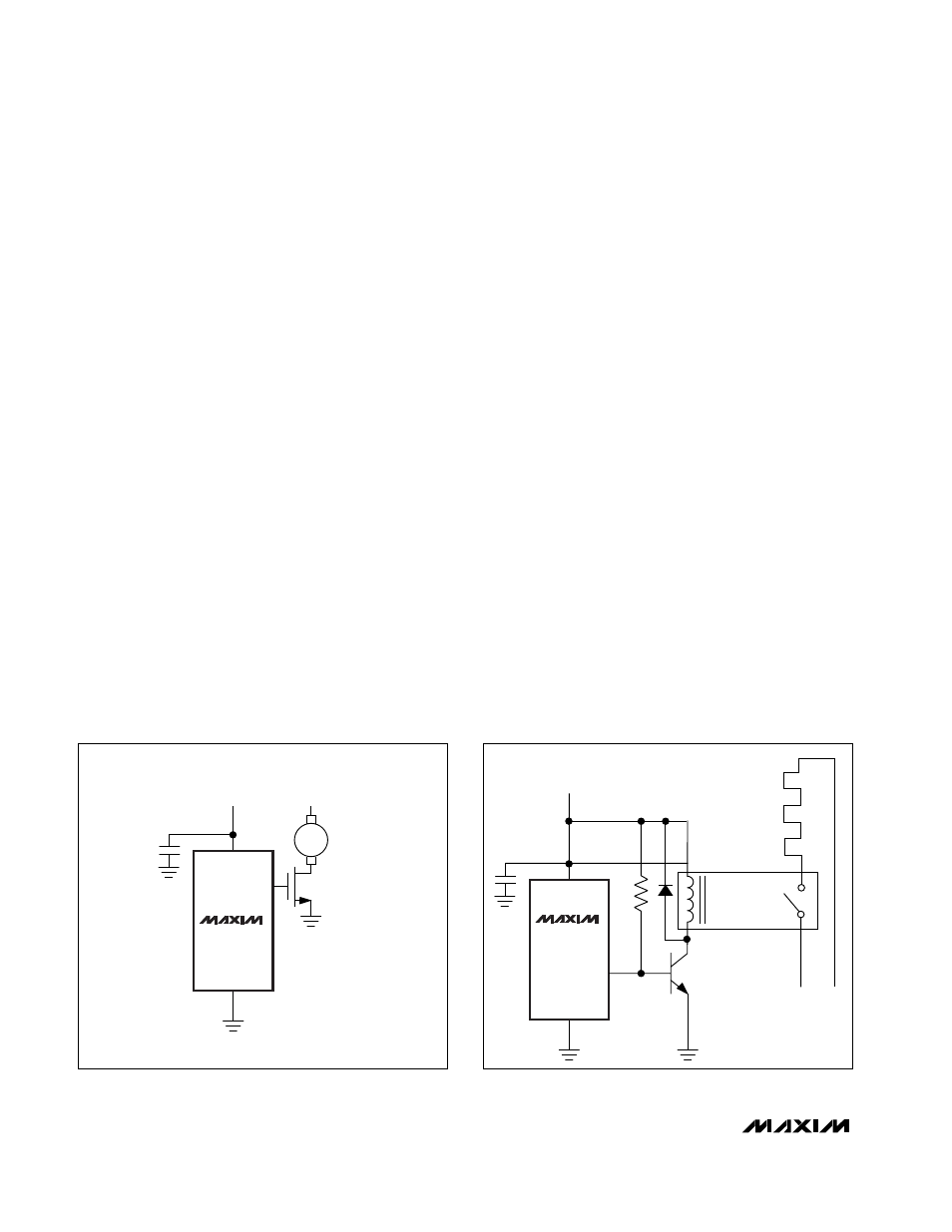
Applications
Figure 7 shows the MAX6625/MAX6626 used as a tem-
perature-triggered fan controller. Figure 8 shows the
MAX6625/MAX6626 used as a thermostat to control a
heating element.
4
6
+V
S
+3V TO +5V
+12V
OT
MAX6625R
MAX6626R
2
12V 300mA
FAN MOTOR
LOGIC LEVEL
MOSFET
5
6
+VS
+3V to +5V
OT
MAX6625P
MAX6626P
RELAY
5VDC, 20mA
125VAC, 1A
2N3904
HEATER
SUPPLY
HEATER
3
4k
Figure 7. Fan Controller
Figure 8. Simple Thermostat