Rainbow Electronics MAX6691 User Manual
Page 5
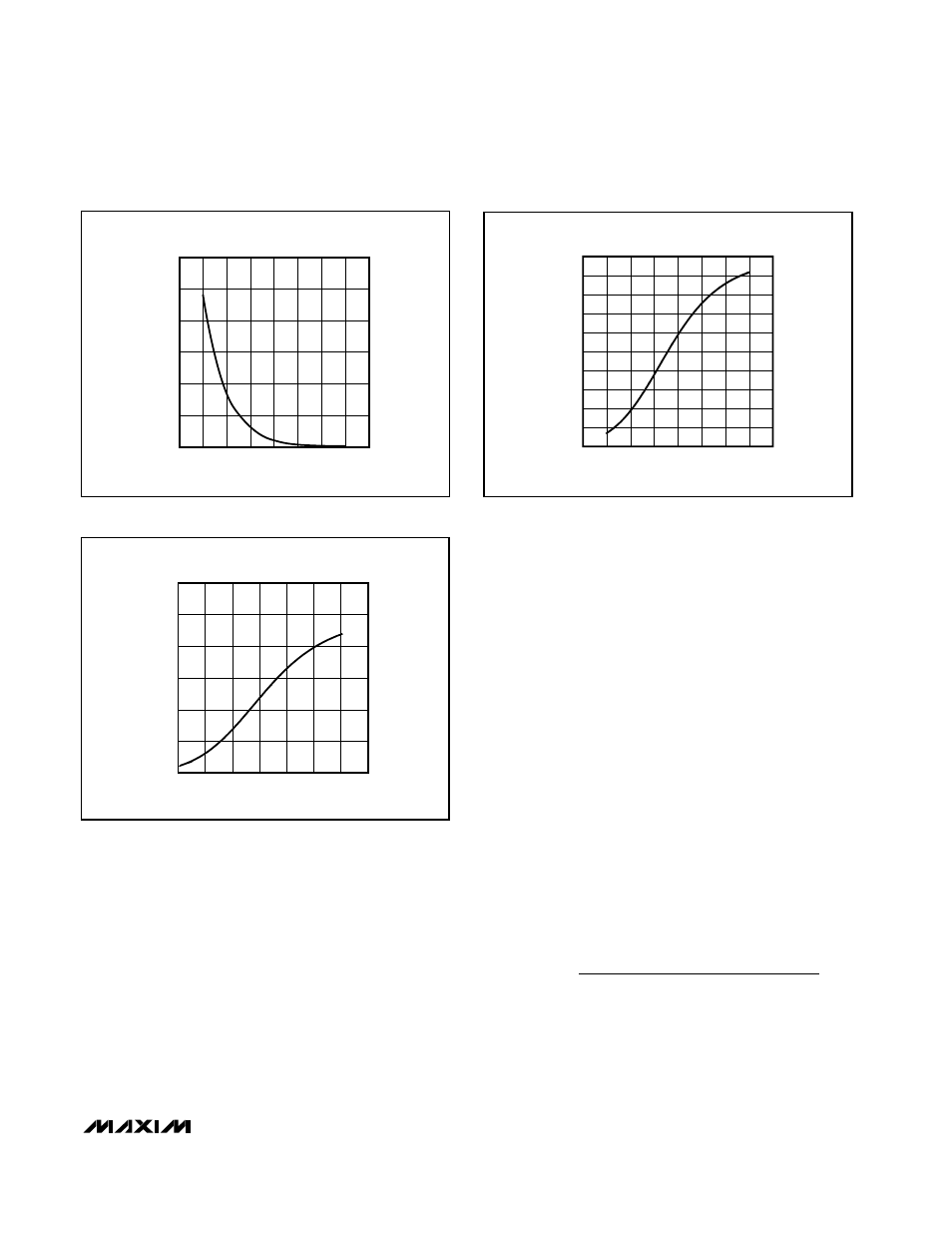
The relationship between temperature and resistance
of an NTC thermistor is highly nonlinear. However, by
connecting the thermistors in series with a properly
chosen resistor (R
EXT
) and using the MAX6691 to mea-
sure the voltage across the resistor, a reasonably linear
transfer function can be obtained over a limited temper-
ature range. Linearity improves for smaller temperature
ranges.
Figures 3 and 4 show typical T
HIGH
/T
LOW
curves for a
standard thermistor in conjunction with values of R
EXT
chosen to optimize linearity over two series resistors
chosen to optimize linearity over two different tempera-
ture ranges.
NTC thermistors are often described by the resistance
at +25°C. Therefore, a 10k
Ω thermistor has a resis-
tance of 10k
Ω at +25°C. When choosing a thermistor,
ensure that the thermistor’s minimum resistance (which
occurs at the maximum expected operating tempera-
ture) in series with R
EXT
does not cause the voltage ref-
erence output current to exceed about 1mA. Some
standard 10k
Ω thermistors with similar characteristics
are listed in Table 1.
Choosing R
EXT
Choose R
EXT
to minimize nonlinearity errors from the
thermistor:
1) Decide on the temperature range of interest (for
example 0°C to +70°C).
2) Find the thermistor values at the limits of the tem-
perature range. R
MIN
is the minimum thermistor
value (at the maximum temperature) and R
MAX
is
the maximum thermistor value (at the minimum tem-
perature). Also find R
MID
, the thermistor resistance
in the middle of the temperature range (+35°C for
the 0°C to +70°C range).
3) Find R
EXT
using the equation below:
Power-Supply Considerations
The MAX6691 accuracy is relatively unaffected by
power-supply coupled noise. In most applications,
R
R
R
R
R
R
R
R
MIN
MAX
MIN
MAX
MIN
MAX
MID
EXT
MIN
=
R
+
(
)
−
×
+
−
2
2
MAX6691
Four-Channel Thermistor Temperature-to-Pulse-
Width Converter
_______________________________________________________________________________________
5
Figure 2. Thermistor Resistance vs. Temperature
0
20
40
60
80
100
120
-40
0
-20
20
40
60
80
100 120
THERMISTOR RESISTANCE
vs. TEMPERATURE
TEMPERATURE (
°C)
THERMISTOR RESISTANCE (k
Ω
)
Figure 3. T
HIGH
/T
LOW
vs. Temperature, R
EXT
= 5110
Ω
T
HIGH
/T
LOW
vs. TEMPERATURE FOR BETATHERM
10K3A1 THERMISTOR WITH R
EXT
= 5110
Ω
TEMPERATURE (
°C)
T
HIGH
/T
LOW
120
100
80
60
40
20
0.2
0.4
0.6
0.8
1.0
1.2
0
0
140
Figure 4. T
HIGH
/T
LOW
vs. Temperature, R
EXT
= 5110
Ω
T
HIGH
/T
LOW
vs. TEMPERATURE FOR BETATHERM
10K3A1 THERMISTOR WITH R
EXT
= 7680
Ω
TEMPERATURE (
°C)
T
HIGH
/T
LOW
100
80
40
60
0
20
-20
0.1
0.2
0.3
0.4
0.5
0.6
0.7
0.8
0.9
1.0
0
-40
120