Assembly instructions (continued) – Wilwood Forged Dynalite Rear Drag Brake Kit User Manual
Page 4
Assembly Instructions (numbers in parenthesis refer to
the part list/diagram on the preceding page): CAUTION: All
mounting bolts must fully engage insert nuts. Be sure to
check that all bolts are either flush or protruding through
flanged side of insert nut after shimming.
•With the slot pointing upward and the mounting ears
pointing towards the rear of the vehicle, install the caliper
mounting bracket (1) to the housing flange using the stock
Original Equipment Manufacturer (OEM) bolts and nuts.
Stock OEM hex nuts that retain the bracket (1) should be
on the wheel side of the bracket. Apply red Loctite® 271
to the stock OEM bolt threads and torque to OEM
specifications. NOTE: Some brackets act as the bearing
retainers, while others help locate the bearing in the axle
housing flange. If the stock bearing plates are still on the
axle, the caliper mounting brackets (1) should be located
between the axle housing flange and the bearing retainer
plate. Make sure the heads of the caliper mounting
bracket insert nuts are FACING OUTWARD TOWARDS
THE WHEEL.
•The rotor (3) has two sides. A flat side and an inset side. Bolt hat (2) to flat side of rotor
(3) using bolts (5). Using an alternating sequence, apply red Loctite® 271 to the threads and
torque bolts to 25 ft-lb. For an added measure of security, the bolts may be safety wired using
standard 0.032 inch diameter stainless steel safety wire as shown in Figure 4. Refer to
Wilwood’s data sheet DS-386 (available at
www.wilwood.com/Pdf/DataSheets/ds386.pdf
) for
complete safety wire installation instructions.
•Align the correct hole pattern in the hat (2) with the stud pattern on the axle flange.
NOTE: Some OEM and after market axles come with stud sizes larger than 0.50” diameter.
Verify stud size and have a qualified machine shop drill the hats to the correct size. Slide the
hat/rotor assembly (2 and 3) over the wheel studs and against the axle flange face.
•NOTE: Please reference the caution statement at the beginning of the assembly instructions.
Mount the caliper (6) over the rotor (3) and onto the caliper mounting bracket (1) using washers
(7) and mounting bolts (8). View the rotor through the top opening of the caliper. The rotor should
be aligned in the center of the caliper. If not, adjust the caliper by using 0.032 inch shims (9)
by placing them between the caliper mounting bracket (1) and the caliper (6). Add as many
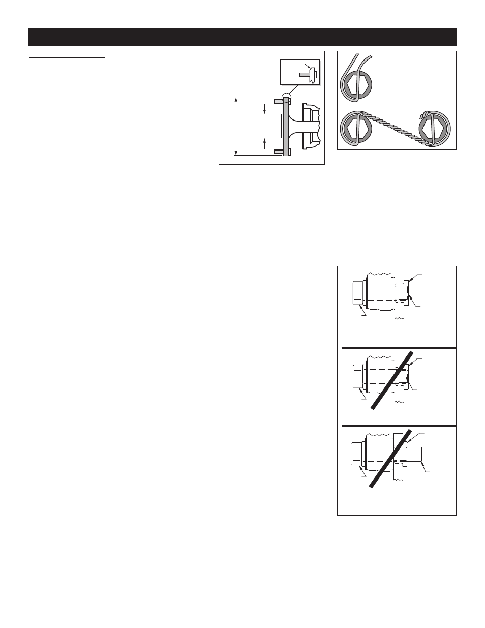
shim washers (9) as necessary to achieve the correct alignment. NOTE: The end of the bolt
must be flush with or slightly protuding from the head of the clinch nut. See Figure 5. Place
spare shims (9) between washer and caliper mounting ear to achieve the proper mounting
fastener configuration. Always use the same amount of shims on both the top and bottom
caliper mounting bolts (8). Apply red Loctite® 271 to the mounting bolt threads (8), torque to
40 ft-lb. Caliper mount bolts may be safety wired for additional security.
•Position the Wilwood disc brake pads (10) into the caliper (6) and fasten with cotter pin (4).
Steel backing plate side of brake pad should face the caliper pistons.
•NOTE: OEM rubber brake hoses generally cannot be adapted to Wilwood calipers. The caliper
inlet fitting is a 1/8-27 NPT. The preferred method is to use steel adapter fittings at the caliper,
either straight, 45 or 90 degree and enough steel braided line to allow for full suspension travel
and turning radius, lock to lock. Carefully route lines to prevent contact with moving
suspension, brake or wheel components. Wilwood hose kits are designed for use in many
different vehicle applications and it is the installer's responsibility to properly route and ensure
adequate clearance and retention for brake hose components.
BEGIN BY SLIDING THE 0.032"
DIAMETER WIRE THROUGH TWO OF
THE HOLES (LEFT) THAT ARE 180°
APART. TWIST THE WIRE AS
SHOWN (BELOW) USING SAFETY
WIRE PLIERS. NOW SLIDE ONE
WIRE THROUGH TWO OF THE
HOLES (180° APART) AND WRAP THE
OTHER WIRE AROUND THE BOLT.
TWIST THE WIRES TOGETHER TO
FORM A PIGTAIL. SEE DS-386 FOR
COMPLETE DETAILS.
Figure 4. Safety Wire Diagram
Assembly Instructions (Continued)
Page 4
END OF BOLT
HEAD
OF BOLT
HEAD
OF BOLT
HEAD
OF BOLT
CORRECT
END OF BOLT IS FLUSH WITH, OR SLIGHTLY
PROTRUDING FROM END OF CLINCH NUT
WRONG
END OF BOLT IS BELOW END OF CLINCH NUT
WRONG
END OF BOLT IS PROTRUDING TOO FAR
FROM END OF CLINCH NUT AND MAY
INTERFERE WITH MOVING PARTS
END OF
CLINCH NUT
END OF
CLINCH NUT
END OF
CLINCH
NUT
END OF BOLT
END OF
BOLT
Figure 5.
Clinch Nut Engagement Diagram
Figure 3. Axle Flange
Maximum Dimension
MAXIMUM
DIA 6.11"
TO FIT
WILWOOD
HAT
3.06”
REGISTER
.050 X 45°
CHAMFER