Wilwood Superlite 4R Big Brake Front Brake Kit (Race) User Manual
Page 3
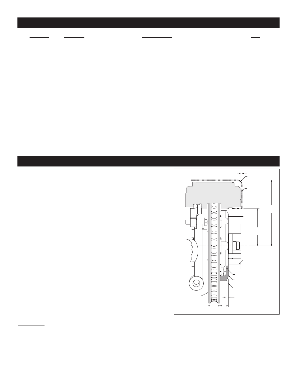
General Information and Disassembly Instructions
Parts List
1
2
3
4
5
6
7
8
9
10
11
12
13
14
15
16
2
4
4
12
4
2
2
16
16
2
4
4
4
16
1
1
250-10689
230-10646
240-0476
240-6320
240-5878
160-11839/40
170-8493
240-10191
230-8473
120-10693/94-RS
230-9183
240-10190
230-9078
240-1159
15H-8114K
220-6746
ITEM NO.
PART NO.
DESCRIPTION
QTY
NOTES: Part Number 230-8390 Rotor Bolt Kit, includes part numbers 230-8473 and 240-10191
Part Number 230-10647 Caliper Bracket Mounting Bolt Kit, includes P/N 230-10646, 240-0476, 240-5878 and 240-6320
Part Number 250-10699 Spindle / Bracket Bolt Kit, includes part numbers 230-9078, 230-9183, 240-1159, 240-10190 & 250-10689
Page 3
See also other documents in the category Wilwood For bicycles:
- Aluminum Tandem M_C Kit with Bracket and Valve (1 page)
- Forged Dynalite Pro Series Front Brake Kit (9 pages)
- W4A Big Brake Rear Parking Brake Kit (9 pages)
- Brake & Clutch Pedal Description (3 pages)
- Brake & Clutch Pedal Description (4 pages)
- Brake & Clutch Pedal Description (5 pages)
- W6A Big Brake Front Brake Kit (Race) (7 pages)
- GP320 Sprint Left Front Brake Kit (6 pages)
- MasterCylinder No: 260-3501 (2 pages)
- Stealth Motorcycle Front Brake Kit (4 pages)
- Billet Superlite 6 Lug Mount Caliper (4 pages)
- MasterCylinder No: 260-9921 (1 page)
- Dynapro Dust-Boot Rear Parking Brake Kit (10 pages)
- W4A Big Brake Rear Brake Kit For OE Parking Brake (8 pages)
- SC1 Single Piston (1 page)
- Forged Narrow Superlite 4R Big Brake Rear Brake Kit For OE Parking Brake (8 pages)
- Dynapro Radial Front Drag Brake Kit (7 pages)
- Dynapro 6 Big Brake Front Brake Kit (Hub) (8 pages)
- Promatrix Front Replacement Rotor Kit (6 pages)
- D8-6 Front Replacement Caliper Kit (6 pages)
- Compact Remote Flange Mount Master Cylinder (6 pages)
- W4A Big Brake Front Brake Kit (Race) (7 pages)
- Forged Dynalite Front Drag Brake Kit (Hat) (8 pages)
- W4A Big Brake Truck Rear Brake Kit (7 pages)
- Dynapro Radial Big Brake Front Brake Kit (Hat) (7 pages)
- Narrow Dynapro Radial Mount (2 pages)
- Dynapro Dust-Boot Pro Series Front Brake Kit (9 pages)
- GM III Single Piston Floater (2 pages)
- Billet Superlite 4R Radial Mount (2 pages)
- Dynapro Dust-Boot Big Brake Front Brake Kit (Hub) (9 pages)
- High Volume Master Cylinder (2 pages)
- D52 Rear Caliper Kits (5 pages)
- Forged Narrow Superlite 6R Big Brake Front Brake Kit (Hat) (7 pages)
- Promatrix Front and Rear Replacement Rotor Kit (5 pages)
- Dynapro Single Front Drag Brake Kit (8 pages)
- Powerlite Radial Mount (2 pages)
- HI-TEMP Brake Fluid (1 page)
- Dynapro SA Lug Drive Dynamic Rear Drag Brake Kit (9 pages)
- MC4 Mechanical (1 page)
- W4A (2 pages)
- EXP600 PLUS Brake Fluid (1 page)
- D154 Front Caliper Kits (6 pages)
- 60 Degree Pedal Description (6 pages)
- Forged Dynalite Pro Series Rear Brake Kit (8 pages)
- Dynapro Dust-Boot (2 pages)