Wilwood TC6R Big Brake Truck Front Brake Kit User Manual
Page 3
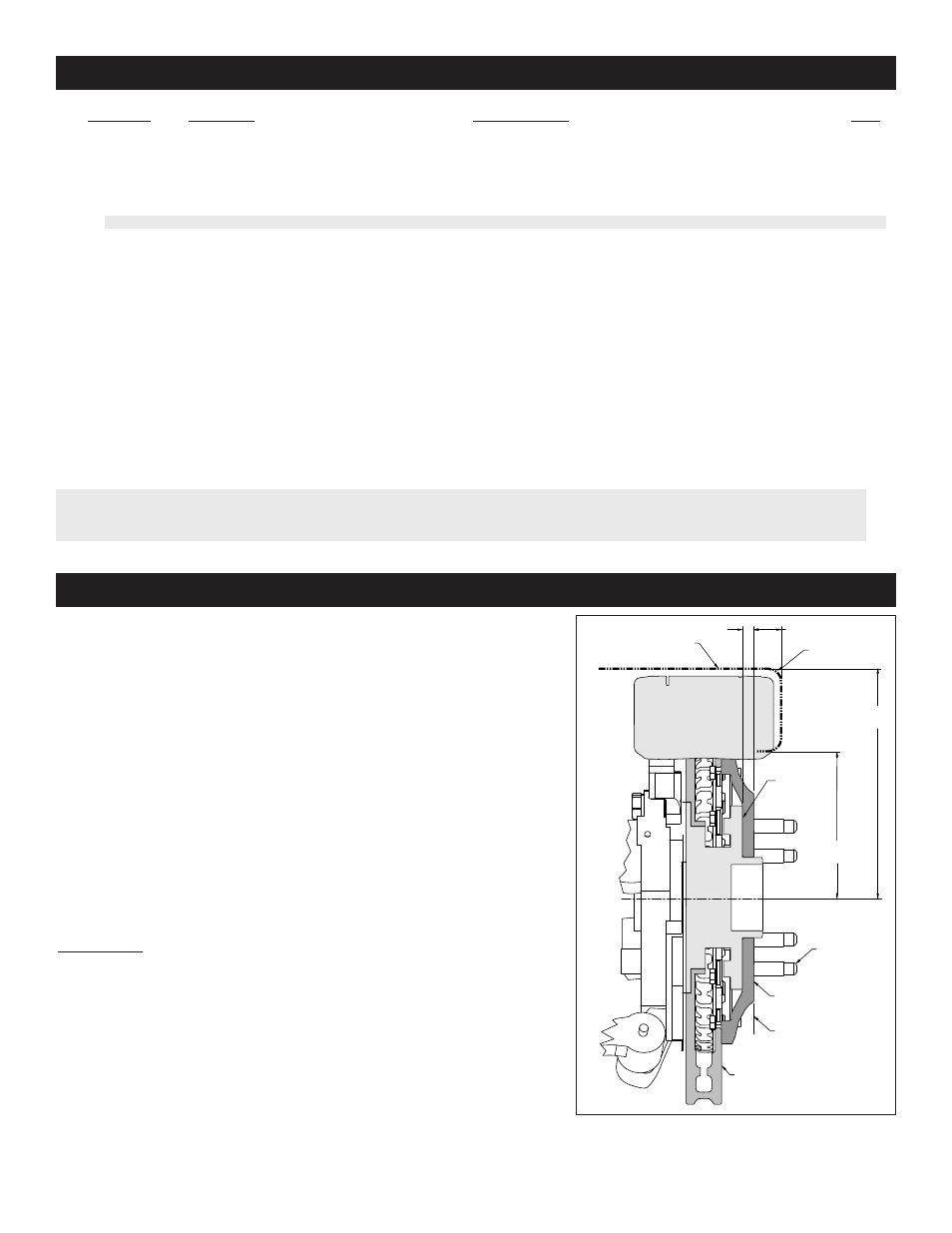
1
2
3
4
5
5A
6
7
8
9
10
11
12
13
14
2
4
4
24
2
2
2
1
24
2
8
12
4
4
4
250-9065
230-8967
240-11855
240-8969
160-8953/54
160-8955/56
170-8960
150-9118K
230-11935
120-8907/08-RS
300-6992
240-1848
230-9080
240-11101
230-9182
ITEM NO.
PART NO.
DESCRIPTION
QTY
NOTES:
Part Number 230-12176 Rotor Bolt Kit, includes part numbers 230-11935
Part Number 230-9077 Bracket Spindle Bolt Kit, includes part numbers 230-8967, 240-11855, 240-8969
Part Number 250-9065 Caliper Bracket Kit, includes P/N’s 230-9080, 230-9182, 240-1848, 240-11101, 250-8961 & 300-6992
Item 5A is an optional item and included with the “-D” kits. Add”-D” to end of part number when ordering.
Wilwood offers an optional Braided Stainless Steel Hose Kit. Order part number 220-8998 (1999-2006), or part number 220-10980
(2007-2011) (neither line included in kit)
Parts List
General Information and Disassembly Instructions
Page 3
- Aluminum Tandem M_C Kit with Bracket and Valve (1 page)
- Forged Dynalite Pro Series Front Brake Kit (9 pages)
- W4A Big Brake Rear Parking Brake Kit (9 pages)
- Brake & Clutch Pedal Description (3 pages)
- Brake & Clutch Pedal Description (4 pages)
- Brake & Clutch Pedal Description (5 pages)
- W6A Big Brake Front Brake Kit (Race) (7 pages)
- GP320 Sprint Left Front Brake Kit (6 pages)
- MasterCylinder No: 260-3501 (2 pages)
- Stealth Motorcycle Front Brake Kit (4 pages)
- Billet Superlite 6 Lug Mount Caliper (4 pages)
- MasterCylinder No: 260-9921 (1 page)
- Dynapro Dust-Boot Rear Parking Brake Kit (10 pages)
- W4A Big Brake Rear Brake Kit For OE Parking Brake (8 pages)
- SC1 Single Piston (1 page)
- Forged Narrow Superlite 4R Big Brake Rear Brake Kit For OE Parking Brake (8 pages)
- Dynapro Radial Front Drag Brake Kit (7 pages)
- Dynapro 6 Big Brake Front Brake Kit (Hub) (8 pages)
- Promatrix Front Replacement Rotor Kit (6 pages)
- D8-6 Front Replacement Caliper Kit (6 pages)
- Compact Remote Flange Mount Master Cylinder (6 pages)
- W4A Big Brake Front Brake Kit (Race) (7 pages)
- Forged Dynalite Front Drag Brake Kit (Hat) (8 pages)
- W4A Big Brake Truck Rear Brake Kit (7 pages)
- Dynapro Radial Big Brake Front Brake Kit (Hat) (7 pages)
- Narrow Dynapro Radial Mount (2 pages)
- Dynapro Dust-Boot Pro Series Front Brake Kit (9 pages)
- GM III Single Piston Floater (2 pages)
- Billet Superlite 4R Radial Mount (2 pages)
- Dynapro Dust-Boot Big Brake Front Brake Kit (Hub) (9 pages)
- High Volume Master Cylinder (2 pages)
- D52 Rear Caliper Kits (5 pages)
- Forged Narrow Superlite 6R Big Brake Front Brake Kit (Hat) (7 pages)
- Promatrix Front and Rear Replacement Rotor Kit (5 pages)
- Dynapro Single Front Drag Brake Kit (8 pages)
- Powerlite Radial Mount (2 pages)
- HI-TEMP Brake Fluid (1 page)
- Dynapro SA Lug Drive Dynamic Rear Drag Brake Kit (9 pages)
- MC4 Mechanical (1 page)
- W4A (2 pages)
- EXP600 PLUS Brake Fluid (1 page)
- D154 Front Caliper Kits (6 pages)
- 60 Degree Pedal Description (6 pages)
- Forged Dynalite Pro Series Rear Brake Kit (8 pages)
- Dynapro Dust-Boot (2 pages)