Assembly instructions (continued) – Wilwood Forged Narrow Superlite 4R Big Brake Rear Brake Kit (Race) User Manual
Page 4
Assembly Instructions (Continued)
Assembly Instructions (numbers in parenthesis refer to the part list/diagram on the preceding pages):
• The caliper mount bracket assembly (1) should be installed first with clean, dry threads on the
mounting bolts. Install the bracket using the original caliper mount bolts. The bracket must
tighten squarely against the outboard side of the caliper mount bosses on the upright. Inspect
for interference from casting irregularities, machining ridges, burrs, etc. Use one thin shim (2)
between the bracket and upright during initial trial fitting. Later, after the caliper, pad, and rotor
alignment has been checked, and any necessary shims have been put in place, the mount
bolts should be coated with red Loctite
®
271 and torqued to 65 ft-lbs.
•Assembly the rotor (3) to the hat (4) using bolts (6), washers (5), and t-nuts (13) as shown in
Figure 1. Apply red Loctite
®
271 to the bolt threads before installing. Finger tighten. After all
t-nuts have been installed, torque bolts in an alternating sequence to 120 in-lbs. Please refer
to Wilwood’s data sheet DS-392 (available at
www.wilwood.com/Pdf/DataSheets/ds392.pdf
) for
complete t-nut bolt kit installation instructions.
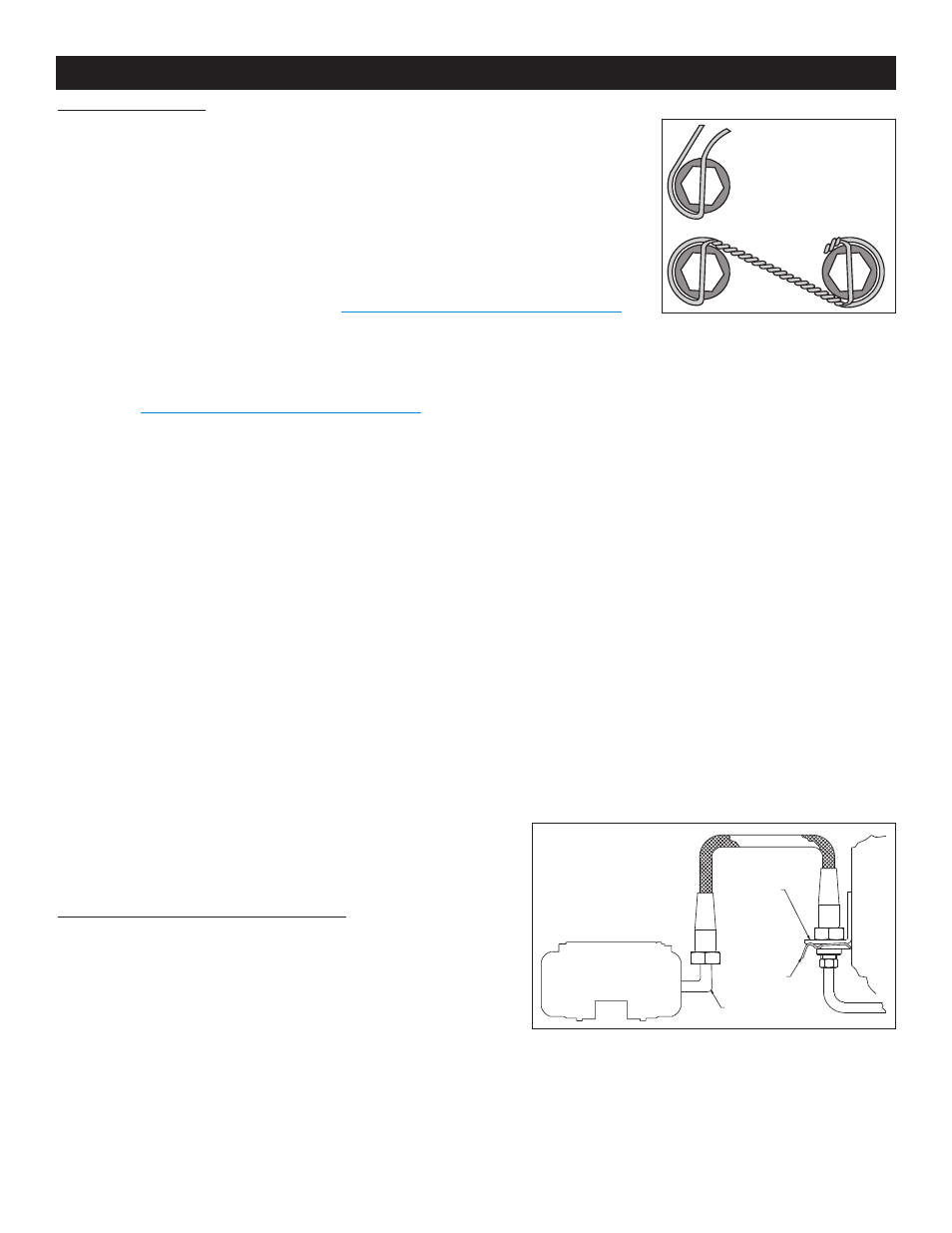
•NOTE: When cross-drilled bolts are supplied with the rotor bolt kits, the additional step of
safety wiring bolts is recommended. Safety wire bolts using standard 0.032 inch diameter
stainless steel safety wire as shown in Figure 3. Refer to Wilwood’s data sheet DS-386
(available at
www.wilwood.com/Pdf/DataSheets/ds386.pdf
) for complete safety wire installation
instructions.
• Align the hole pattern on the hat and rotor assembly (3 and 4) with the stud pattern on the axle flange. Slide the hat/rotor assembly
over the wheel studs and against the axle flange face. Check to be sure the hat seats squarely against the axle flange face. The axle
flange must be free from any rust, debris, casting burrs, machining irregularities, etc. Use several lug nuts to hold the rotor and hat
firmly against the axle flange during the next phases of the installation and clearance checking procedures.
• Install one shim (11) over each stud (10) on the radial mount bracket (1). Slide the caliper (7) in place over the studs and rotor and
install the washer (9) and lock nut (8) to hold the caliper in place. The caliper bleed screws should be pointing up. Snug the lock nuts
(8) and check that the rotor (3) is centered in the caliper (7). Add or subtract .015" shims (2) as necessary between the caliper mount
bracket and the caliper mount bosses on the upright assembly to center the caliper.
• Remove the caliper center bridge pad retainer bolt, nut, and tube from the caliper. Slide the brake pads (12) into place. They should
install easily without interference. Check that the outside radius of the brake pad is aligned with the outside diameter radius of the rotor
face. Add or subtract shims (11) between the caliper and mount bracket to gain the proper alignment. Reinstall the center bridge pad
retainer tube, bolt, and lock nut. The locknut should be snug without play in the bolt or tube. Be cautious not to over tighten.
• Remove the lug nuts that were holding the hat in place. Install the wheel and torque the lug nuts to specification. Check to see that
the wheel rotates freely without interference.
• Once all clearances have been checked, remove the wheel, caliper, hat, and rotor from the axle flange. Secure the caliper mounting
bracket (1) to the axle flange body using red Loctite
®
271. Torque the bolts to 65 ft-lbs. Reinstall the hat and rotor assembly
and again use several lug nuts to hold it in place. Lubricate caliper mounting studs and nuts with lightweight oil, reinstall the caliper,
torque the caliper nuts (8) to 30 ft-lbs.
• Install the wheel and torque the lug nuts to specification.
• If necessary, adjust the parking brake shoes to factory specifications.
Stock Brake Line Disassembly Instructions
•Unbolt banjo bolt from back of caliper.
•Unbolt rubber hose from hard line at frame.
•Pull the clip that holds the rubber hose to the bracket at the frame.
•Install Wilwood’s optional stainless steel braided flex line hose kit, part
number 220-8173 for C-5, 220-9101 for C-6 (NOT included in kit), see
Figure 4. NOTE: OEM rubber brake hoses generally cannot be adapted
to Wilwood calipers. The caliper inlet fitting is a 1/8-27 NPT. The preferred
method is to use steel adapter fittings at the caliper, either straight, 45 or
90 degree and enough steel braided line to allow for full suspension travel
and turning radius, lock to lock. Carefully route lines to prevent contact with moving suspension, brake or wheel components.
Wilwood hose kits are designed for use in many different vehicle applications and it is the installer's responsibility to properly route and
ensure adequate clearance and retention for brake hose components.
FLEXLINE
BRACKET
CLIP
FRAME
HARDLINE
WILWOOD
SL4 CALIPER
90° ELBOW
Figure 4. Brake Line Diagram
BEGIN BY SLIDING THE 0.032"
DIAMETER WIRE THROUGH TWO OF
THE HOLES (LEFT) THAT ARE 180°
APART. TWIST THE WIRE AS
SHOWN (BELOW) USING SAFETY
WIRE PLIERS. NOW SLIDE ONE
WIRE THROUGH TWO OF THE
HOLES (180° APART) AND WRAP THE
OTHER WIRE AROUND THE BOLT.
TWIST THE WIRES TOGETHER TO
FORM A PIGTAIL. SEE DS-386 FOR
COMPLETE DETAILS.
Figure 3. Safety Wire Diagram
Page 4