Assembly instructions – Wilwood Dynapro 6 Big Brake Front Brake Kit (Hat) User Manual
Page 4
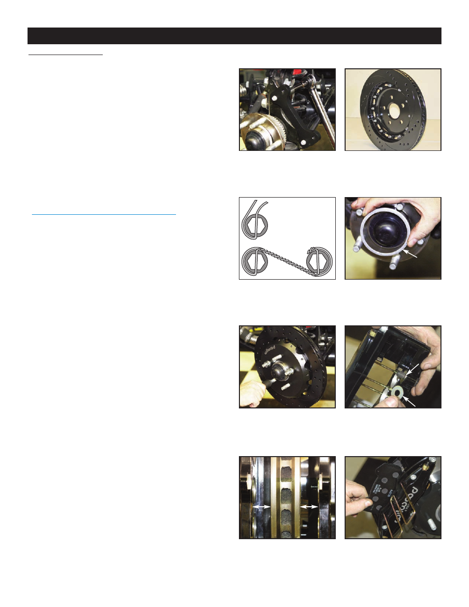
Assembly Instructions (numbers in parenthesis refer to the parts list and Figure 1 on the preceding pages):
• Orient the caliper mount bracket (1) as shown in Figure 1 and
Photo 1, and install using bolts (2) and washers (3). Temporarily
tighten the mounting bolts. NOTE: The bracket must fit squarely
against the mount bosses on the upright.
Inspect for
interference from casting irregularities, machining ridges, burrs,
etc. Remove bolts one at a time, apply red Loctite
®
271 to the
threads and torque to 60 ft-lb.
• Orient the rotor (5) and the hat (6) as shown in Figure 1 and
Photo 2. Attach rotor to hat using bolts (8) and washers (7).
Using an alternating sequence, apply red Loctite® 271 to the
threads and torque bolts to 155 in-lb. For an added measure of
security, the bolts may be safety wired using standard 0.032 inch
diameter stainless steel safety wire as shown in Figure 3.
Please refer to Wilwood’s data sheet DS-386 (available at
www.wilwood.com/Pdf/DataSheets/ds386.pdf
) for complete
safety wire installation instructions.
•Slide the rotor registration adapter (4) onto the axle register on
the axle hub with the smaller O.D. facing toward the rotor/hat
(5/6), Photo 3. Slide the hat/rotor assembly onto the axle hub,
Photo 4. NOTE: The hat must fit flush against the axle hub
flange or excessive rotor run out may result. Install three lug nuts
(finger tight) to keep the hat/rotor assembly in place while
continuing with the installation.
•NOTE: This kit contains distinct right and left hand calipers that
must be mounted in a specific direction, as described below.
Mount the caliper (9) onto the caliper mounting bracket (1) using
bolts (11) and washers (10), as shown in Figure 1. Initially
place one each .016” thick shim (12) and .035” thick shim (13) on
each bolt between the caliper and the bracket, Figure 1 and
Photo 5. Ensure that the caliper is mounted so the largest pistons
are at the rotor exit end of the caliper, in relation to the direction of
rotor rotation. Temporarily tighten the mounting bolts and view
the rotor (5) through the top opening of the caliper. The rotor
should be centered in the caliper, Photo 6. If not, adjust by
adding or subtracting shims (12 and/or 13) between the bracket
and the caliper. Always use the same amount of shims on each
of the two mounting bolts. Once the caliper alignment is correct,
remove the bolts one at a time, apply red Loctite® 271 to bolt
threads, and torque to 35 ft-lb.
•Install the disc brake pads (14) into the caliper, with the friction
material facing the rotor (5), and secure in place using the pad
clip retainer (15), Photo 7.
•Temporarily install wheel and torque lug nuts to manufacturer’s
specification. Ensure that the wheel rotates freely without any
interference.
Assembly Instructions
Photo 1
Photo 4
Photo 3
Photo 2
Page 4
Small
O.D.
toward
rotor/hat
Photo 5
Photo 7
Photo 6
BEGIN BY SLIDING THE 0.032"
DIAMETER WIRE THROUGH TWO OF
THE HOLES (LEFT) THAT ARE 180°
APART. TWIST THE WIRE AS
SHOWN (BELOW) USING SAFETY
WIRE PLIERS. NOW SLIDE ONE
WIRE THROUGH TWO OF THE
HOLES (180° APART) AND WRAP THE
OTHER WIRE AROUND THE BOLT.
TWIST THE WIRES TOGETHER TO
FORM A PIGTAIL. SEE DS-386 FOR
COMPLETE DETAILS.
Figure 3. Safety Wire Diagram