Parts list general information – Wilwood Dynapro Low-Profile Rear Parking Brake Kit User Manual
Page 3
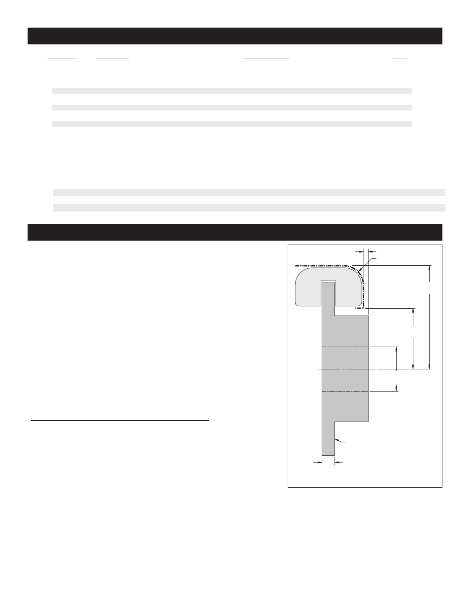
Parts List
General Information
Page 3
1
2
3
3A
4A
4AA
4B
4BB
5
6
7
8
9
1
2
2
2
2
2
2
2
4
4
16
1
2
249-11432/33
300-11337
160-11365
160-11376/77-BK
120-11370
120-11370-RD
120-12160
120-12160-RD
240-10190
230-10025
240-1159
150-11363K
300-9636
ITEM NO.
PART NO.
DESCRIPTION
QTY
NOTES: Part Number 230-11861 Caliper Mounting Bolt Kit, includes P/N’s 230-10025, 240-10190 and 240-1159
Item 3A is an optional item and is included in the “-D” drilled rotor kits. Add ”-D” to end of part number when ordering.
Kit will contain either caliper, 4A or 4B.
Item 4AA and 4BB are optional items and included in the “-R” red caliper kits, Add “-R” to end of part number when ordering.
See also other documents in the category Wilwood For bicycles:
- Aluminum Tandem M_C Kit with Bracket and Valve (1 page)
- Forged Dynalite Pro Series Front Brake Kit (9 pages)
- W4A Big Brake Rear Parking Brake Kit (9 pages)
- Brake & Clutch Pedal Description (3 pages)
- Brake & Clutch Pedal Description (4 pages)
- Brake & Clutch Pedal Description (5 pages)
- W6A Big Brake Front Brake Kit (Race) (7 pages)
- GP320 Sprint Left Front Brake Kit (6 pages)
- MasterCylinder No: 260-3501 (2 pages)
- Stealth Motorcycle Front Brake Kit (4 pages)
- Billet Superlite 6 Lug Mount Caliper (4 pages)
- MasterCylinder No: 260-9921 (1 page)
- Dynapro Dust-Boot Rear Parking Brake Kit (10 pages)
- W4A Big Brake Rear Brake Kit For OE Parking Brake (8 pages)
- SC1 Single Piston (1 page)
- Forged Narrow Superlite 4R Big Brake Rear Brake Kit For OE Parking Brake (8 pages)
- Dynapro Radial Front Drag Brake Kit (7 pages)
- Dynapro 6 Big Brake Front Brake Kit (Hub) (8 pages)
- Promatrix Front Replacement Rotor Kit (6 pages)
- D8-6 Front Replacement Caliper Kit (6 pages)
- Compact Remote Flange Mount Master Cylinder (6 pages)
- W4A Big Brake Front Brake Kit (Race) (7 pages)
- Forged Dynalite Front Drag Brake Kit (Hat) (8 pages)
- W4A Big Brake Truck Rear Brake Kit (7 pages)
- Dynapro Radial Big Brake Front Brake Kit (Hat) (7 pages)
- Narrow Dynapro Radial Mount (2 pages)
- Dynapro Dust-Boot Pro Series Front Brake Kit (9 pages)
- GM III Single Piston Floater (2 pages)
- Billet Superlite 4R Radial Mount (2 pages)
- Dynapro Dust-Boot Big Brake Front Brake Kit (Hub) (9 pages)
- High Volume Master Cylinder (2 pages)
- D52 Rear Caliper Kits (5 pages)
- Forged Narrow Superlite 6R Big Brake Front Brake Kit (Hat) (7 pages)
- Promatrix Front and Rear Replacement Rotor Kit (5 pages)
- Dynapro Single Front Drag Brake Kit (8 pages)
- Powerlite Radial Mount (2 pages)
- HI-TEMP Brake Fluid (1 page)
- Dynapro SA Lug Drive Dynamic Rear Drag Brake Kit (9 pages)
- MC4 Mechanical (1 page)
- W4A (2 pages)
- EXP600 PLUS Brake Fluid (1 page)
- D154 Front Caliper Kits (6 pages)
- 60 Degree Pedal Description (6 pages)
- Forged Dynalite Pro Series Rear Brake Kit (8 pages)
- Dynapro Dust-Boot (2 pages)