Assembly instructions (continued) – Wilwood Dynapro SA Lug Drive Dynamic Rear Drag Brake Kit User Manual
Page 5
Assembly Instructions (Continued)
40 ft-lb. For an added measure of security, the bolts may be safety wired using standard 0.032 inch
diameter stainless steel safety wire as shown in Figure 4. Please refer to Wilwood’s data sheet DS-
386 (available at
www.wilwood.com/Pdf/DataSheets/ds386.pdf
) for complete safety wire installation
instructions. Repeat this procedure for the second caliper.
•Install the disc brake pads (10) into the calipers, with the friction material facing the rotor, and secure
in place with the pad clip retainer (11), Photo 7.
•Temporarily install the wheel and torque lug nuts to manufacturer’s specification. Ensure that the
wheel rotates freely without any interference.
•NOTE: OEM rubber brake hoses generally cannot be adapted to Wilwood calipers. The caliper inlet
fitting is a 1/8-27 NPT. The preferred method is to use steel adapter fittings at the caliper, either
straight, 45 or 90 degree and enough steel braided line to allow for full suspension travel. Carefully
route lines to prevent contact with moving suspension, brake or wheel components. NOTE:
Wilwood hose kits are designed for use in many different vehicle applications and it is the installer's
responsibility to properly route and ensure adequate clearance and retention for brake hose
components.
•Specified brake hose kits may not work with all Years, Makes and Models of vehicle that this brake
kit is applicable to, due to possible OEM manufacturing changes during a production vehicle's life. It
is the installer's responsibility to ensure that all fittings and hoses are the correct size and length, to
ensure proper sealing and that they will not be subject to crimping, strain and abrasion from vibration
or interference with suspension components, brake rotor or wheel.
•In absence of specific instructions for brake line routing, the installer must use his best professional
judgment on correct routing and retention of lines to ensure safe operation. Test vehicle brake system
per the 'minimum test' procedure stated within this document before driving. After road testing, inspect
for leaks and interference. Initially after install and testing, perform frequent checks of the vehicle
brake system and lines before driving, to confirm that there is no undue wear or interference not
apparent from the initial test. Afterwards, perform periodic inspections for function, leaks and wear in
a interval relative to the usage of vehicle.
• Bleed the brake system, referring to the additional the information and recommendations on page 7 for proper bleeding instructions.
Check system for leaks after bleeding.
•Install the wheel and torque lug nuts to manufacturer’s specifications.
Page 5
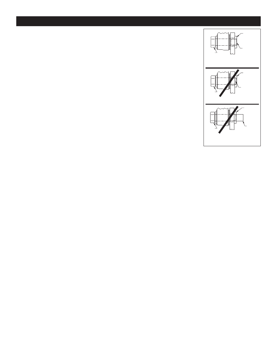
END OF BOLT
HEAD
OF BOLT
HEAD
OF BOLT
HEAD
OF BOLT
CORRECT
END OF BOLT IS FLUSH WITH, OR SLIGHTLY
PROTRUDING FROM END OF CLINCH NUT
WRONG
END OF BOLT IS BELOW END OF CLINCH NUT
WRONG
END OF BOLT IS PROTRUDING TOO FAR
FROM END OF CLINCH NUT AND MAY
INTERFERE WITH MOVING PARTS
END OF
CLINCH NUT
END OF
CLINCH NUT
END OF
CLINCH
NUT
END OF BOLT
END OF
BOLT
Figure 5. Clinch Nut
Engagement Diagram