Wilwood Dynapro Radial Big Brake Front Brake Kit (Hat) User Manual
Page 3
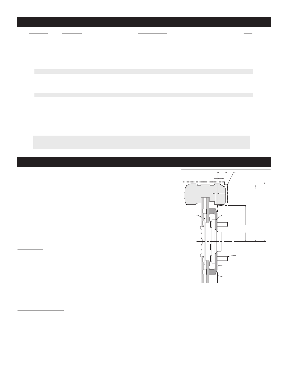
General Information, Disassembly, and Assembly Instructions
Parts List
1
2
3
4
5
6
7
7A
8
9
10
11
11A
12
13
14
15
2
4
1
4
4
8
2
2
2
4
16
2
2
4
4
16
4
250-8270
230-8275
150-8946K
240-0476
300-8273
240-5878
160-5843
160-7103/04
170-8269
300-8259
230-11935
120-7376
120-7376-RD
230-9183
240-10190
240-1159
230-9078
ITEM NO.
PART NO.
DESCRIPTION
QTY
NOTES: Part Number 230-12177 Rotor Bolt Kit, includes part number 230-11935
Part Number 250-8271 Caliper Bracket Mounting Bolt Kit, includes P/N’s 230-9183, 230-9078, 240-1159, 240-10190 & 250-8270
Part Number 230-8277 Spindle Bracket Mounting Bolt Kit, includes P/N’s 230-8275, 240-0476, 240-5878 & 300-8273
Item 7A is an optional item and is included with the (D) drilled rotor kits. Add -D to end of part number when ordering.
Item 11A is an optional item and is included in the (R) red caliper kits. Add -R to end of part number when ordering.
Wilwood offers an optional Braided Stainless Steel Hose Kit. Order part number 220-8339 (not included in kit)
Page 3
- Aluminum Tandem M_C Kit with Bracket and Valve (1 page)
- Forged Dynalite Pro Series Front Brake Kit (9 pages)
- W4A Big Brake Rear Parking Brake Kit (9 pages)
- Brake & Clutch Pedal Description (3 pages)
- Brake & Clutch Pedal Description (4 pages)
- Brake & Clutch Pedal Description (5 pages)
- W6A Big Brake Front Brake Kit (Race) (7 pages)
- GP320 Sprint Left Front Brake Kit (6 pages)
- MasterCylinder No: 260-3501 (2 pages)
- Stealth Motorcycle Front Brake Kit (4 pages)
- Billet Superlite 6 Lug Mount Caliper (4 pages)
- MasterCylinder No: 260-9921 (1 page)
- Dynapro Dust-Boot Rear Parking Brake Kit (10 pages)
- W4A Big Brake Rear Brake Kit For OE Parking Brake (8 pages)
- SC1 Single Piston (1 page)
- Forged Narrow Superlite 4R Big Brake Rear Brake Kit For OE Parking Brake (8 pages)
- Dynapro Radial Front Drag Brake Kit (7 pages)
- Dynapro 6 Big Brake Front Brake Kit (Hub) (8 pages)
- Promatrix Front Replacement Rotor Kit (6 pages)
- D8-6 Front Replacement Caliper Kit (6 pages)
- Compact Remote Flange Mount Master Cylinder (6 pages)
- W4A Big Brake Front Brake Kit (Race) (7 pages)
- Forged Dynalite Front Drag Brake Kit (Hat) (8 pages)
- W4A Big Brake Truck Rear Brake Kit (7 pages)
- Narrow Dynapro Radial Mount (2 pages)
- Dynapro Dust-Boot Pro Series Front Brake Kit (9 pages)
- GM III Single Piston Floater (2 pages)
- Billet Superlite 4R Radial Mount (2 pages)
- Dynapro Dust-Boot Big Brake Front Brake Kit (Hub) (9 pages)
- High Volume Master Cylinder (2 pages)
- D52 Rear Caliper Kits (5 pages)
- Forged Narrow Superlite 6R Big Brake Front Brake Kit (Hat) (7 pages)
- Promatrix Front and Rear Replacement Rotor Kit (5 pages)
- Dynapro Single Front Drag Brake Kit (8 pages)
- Powerlite Radial Mount (2 pages)
- HI-TEMP Brake Fluid (1 page)
- Dynapro SA Lug Drive Dynamic Rear Drag Brake Kit (9 pages)
- MC4 Mechanical (1 page)
- W4A (2 pages)
- EXP600 PLUS Brake Fluid (1 page)
- D154 Front Caliper Kits (6 pages)
- 60 Degree Pedal Description (6 pages)
- Forged Dynalite Pro Series Rear Brake Kit (8 pages)
- Dynapro Dust-Boot (2 pages)