Assembly instructions – Wilwood W4A Big Brake Rear Parking Brake Kit User Manual
Page 4
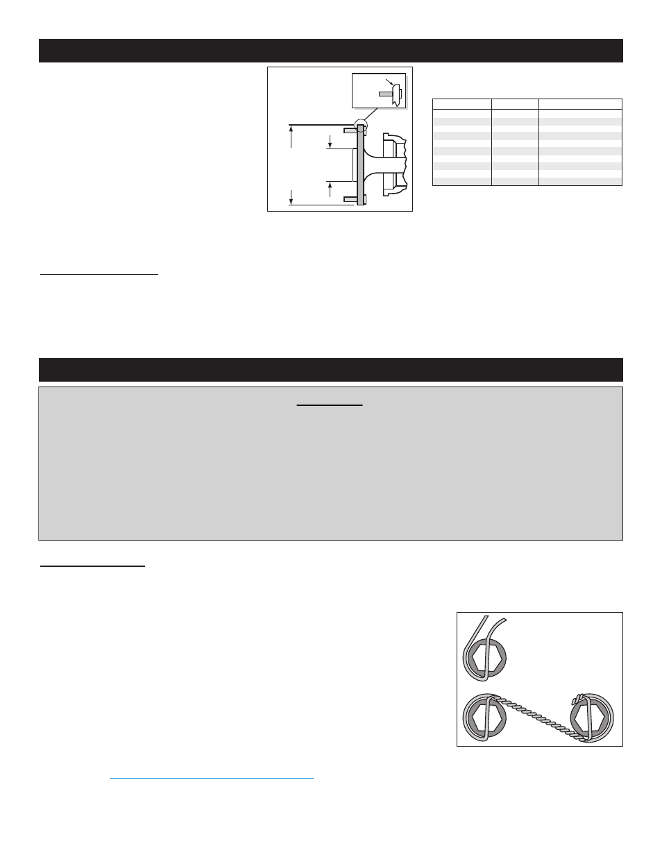
• Dimension from wheel side of axle flange to
wheel side of axle housing flange (see
Figure 6, lower right hand corner). This
dimension is critical to ensure proper
alignment of the rotor to the caliper, and
should match offset given in the kit
description.
• Verify that the wheel axle stud size is 0.50”
diameter. The Wilwood hats utilized in these
kits are drilled for 0.50” diameter wheel
studs.
• Maximum axle flange diameter must be no
larger than 6.61” w/.050” x 45° chamfer (see
Figure 3).
Disassembly Instructions
•Disassemble the original equipment rear brakes:
Raise the rear wheels off the ground and support the rear suspension according to the vehicle manufacturer’s instructions.
Completely disassemble the stock brake system down to the bare axle. Degrease and remove any dings and burrs on housing
flange as well as axle flange which may interfere with brake assembly.
Assembly Instructions (numbers in parenthesis refer to the parts list/diagram on the preceding pages): CAUTION: All mounting bolts
must fully engage insert nuts. Be sure to check that all bolts are either flush or protruding through flanged side of insert nut after
shimming.
•Slide the bracket kit assembly (1) onto the housing flange and then insert the axle assembly
through the center hole of the bracket kit assembly (1). Secure using the stock Original
Equipment Manufacturer (OEM) bolts and nuts. Stock OEM hex nuts that retain the bracket
kit assembly (1) should be on the wheel side of the bracket. Apply red Loctite® 271 to the
stock OEM bolt threads and torque to OEM specifications. Make sure the bracket kit assembly
(1) brake pads are FACING OUTWARD TOWARDS THE WHEEL.
•With the larger I.D. side of the rotor (3) facing away from the hat (2), bolt rotor (3) to hat (2)
through the backside of the rotor using washers (4) and bolts (5). Using an alternating
sequence, apply red Loctite® 271 to the threads and torque bolts to 140 in-lb. For an added
measure of security, the bolts may be safety wired using standard 0.032 inch diameter
stainless steel safety wire as shown in Figure 4. Please refer to Wilwood’s data sheet DS-386
(available at
www.wilwood.com/Pdf/DataSheets/ds386.pdf
) for complete safety wire
installation instructions.
General Information (Continued) and Disassembly Instructions
Figure 3. Axle Flange
Maximum Dimension
MAXIMUM
DIA 6.61"
TO FIT
WILWOOD
HAT
2.80”
REGISTER
.050 X 45°
CHAMFER
BEGIN BY SLIDING THE 0.032"
DIAMETER WIRE THROUGH TWO OF
THE HOLES (LEFT) THAT ARE 180°
APART. TWIST THE WIRE AS
SHOWN (BELOW) USING SAFETY
WIRE PLIERS. NOW SLIDE ONE
WIRE THROUGH TWO OF THE
HOLES (180° APART) AND WRAP THE
OTHER WIRE AROUND THE BOLT.
TWIST THE WIRES TOGETHER TO
FORM A PIGTAIL. SEE DS-386 FOR
COMPLETE DETAILS.
Figure 4. Safety Wire Diagram
Page 4
Assembly Instructions
IMPORTANT:
• To ensure maximum performance from your parking brake system, the cables must be routed as straight as
possible. Bends in the cable can significantly reduce efficiency and thus reduce pull force at the brake. Tight
bends must be avoided with a minimum recommended bend radius of 6" to 8".
• Cables should be properly restrained to prevent "straightening" of bends when tension is applied. Restrain
movement of cable by affixing the cable sheath to body or chassis by fitting cable clamps at various points
over the length of cable or by using original equipment cable attachments points. The clamping method
chosen will require that cable sheath be held tightly without movement, crushing or causing interference to the
internal cable.
• Cables must be initially pre-stretched by multiple applications of the brake handle, then re-adjusted to correct
tension.
Table 1. Center Register Adapters
This kit includes a 3.06” center I.D. hat or rotor assembly and a 2.80” hub
register adapter ring to accommodate the installation of this kit on axles of
either dimension. For axles with different center register diameters, please
consult the table below for optional adapter ring sizes.
PART NO.
REGISTER I.D.
NOTE
NO ADAPTER USED
300-11732
300-11962
300-11338
300-11337
300-11532
300-11803
300-11901
300-11653
300-11339
3.06”
2.86”
2.84”
2.82”
2.80”
2.78”
2.52”
2.50”
2.18”
2.00”
ROTOR CENTER HOLE I.D.
OPTIONAL
OPTIONAL
OPTIONAL
SUPPLIED WITH KIT
OPTIONAL
OPTIONAL
OPTIONAL
OPTIONAL
OPTIONAL (Machine to fit I.D.)