Motor driven gate installation – Grain Systems Bucket Elevtors, Conveyors, Series II Sweeps PNEG-765 User Manual
Page 6
6
PNEG-765 Gate Manual
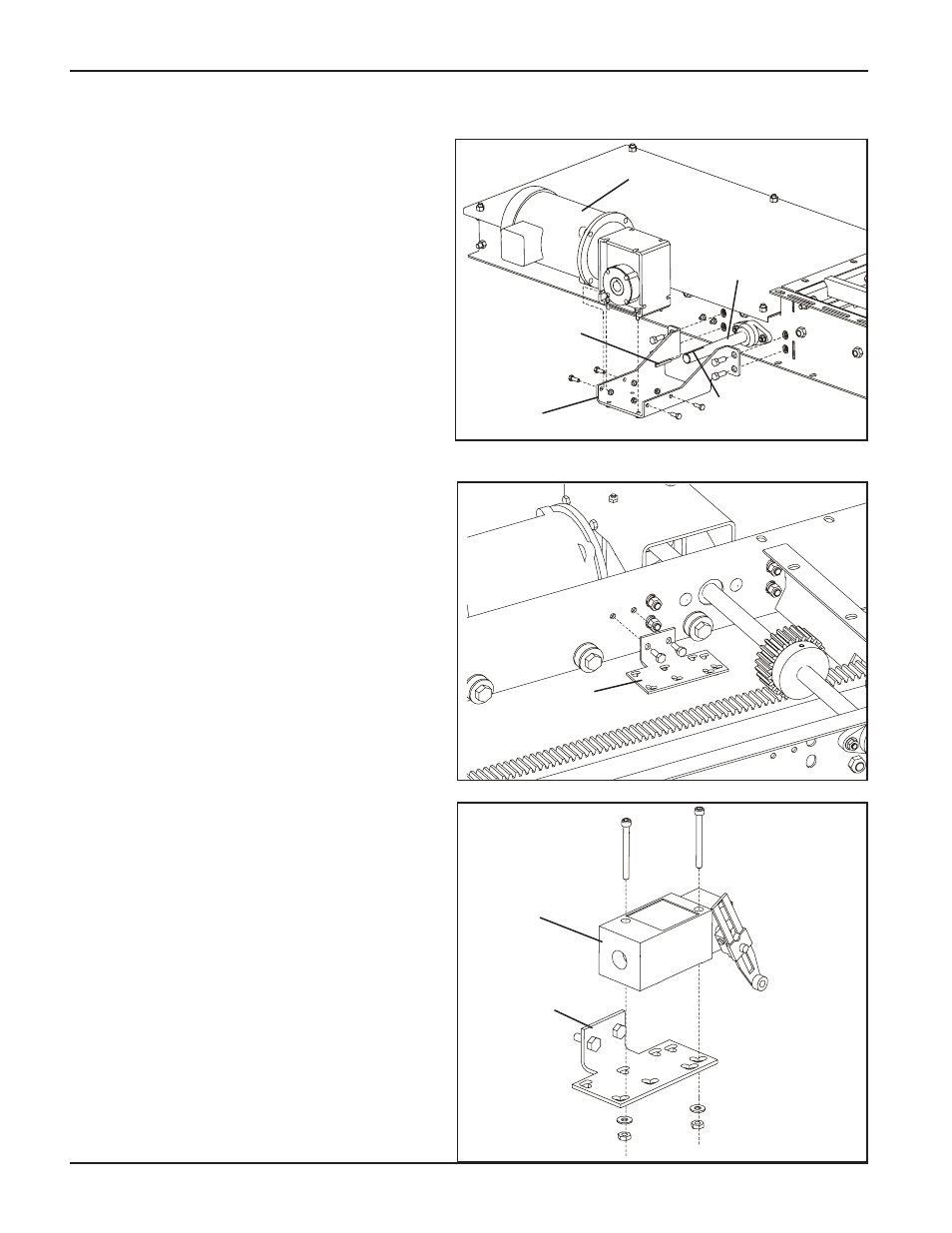
Install Motor Bracket
1. Install the motor bracket to the gate. Then
attach the motor to the bracket as shown
in Figure 3, using the provided hardware.
1. Using limit switches that are available in
Nema 4 or explosion proof standards,
achieves accurate positioning of these
gates. Limit Switches are located on both
sides of the frame to detect when the gate
is totally open or closed.
2. Attach the switch brackets to the inside of
the gate as shown using hardware
provided. (See Figure 4.) Attach limit
switch to the bracket as shown. (See
Figure 5.)
3. After switches are securely fastened.
Adjust lever arms so they come in contact
with tripper blocks on underneath side of
slide plate.
4. Disconnect the power at the electrical
panel, run the proper gauge electrical wire
to the motors and limit switches. (See
Wiring Diagram on page 9.) Be sure that
the limit switches are adjusted
properly before operating the gate!
Turn the power back on and CAUTIOUSLY
operate the gate, opening and closing the
gate slide, making the necessary
adjustments to the limit switch arms to
assure complete opening and closing of
the gate.
5. Motor driven gates are available in both
TEFC and explosion proof configurations.
Install Limit Switch
Motor Driven Gate Installation
Figure 3
Figure 4
Figure 5
Switch
Bracket
Limit
Switch
Switch
Bracket
Motor
Motor
Bracket
Key
Shaft
Keyway