Banks Power Chevy_GMC Trucks: Diesel ’93 - 96 6.5L Power Systems- Stinger System '93-early '94 (non-cat) & '94-up ( w_ cat) Pickups & Suburbans w_ factory turbo option User Manual
Page 9
9
extended cab and crew cab models: The extension
pipe will install between the turbine outlet pipe
and the intermediate pipe. Temporarily place the
intermediate pipe, muffler and tailpipe in place
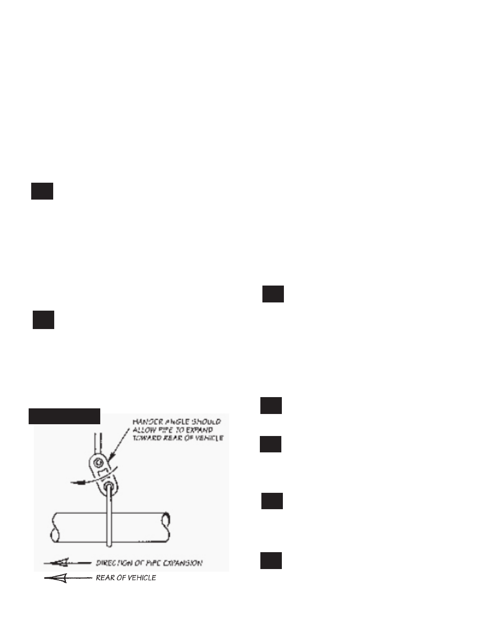
using the hangers and hanger clamps. position the
components such that the turbine outlet pipe and
the intermediate pipe are in alignment with each
other and the rubber hangers are swung slightly
forward (see Figure 6). Measure the distance from
the outlet end of the turbine outlet pipe to the
inlet of the intermediate pipe. add approximately
5” to allow for the two slip joints, and cut the
extension pipe to the appropriate length (crew cab
applications may not need to be cut).
16.
adjust the position of the complete exhaust
system to provide maximum clearance to the
frame and other components. check the alignment
of the muffler and the tailpipe. The muffler should
be straight and level, and the rubber hangers should
be swung forward toward the front of the vehicle
3
⁄
4
”
to 1” to allow for expansion of the pipes. See Figure
6. When alignment and clearances are proper,
tighten all clamps including the factory v-band
clamp on the turbine outlet pipe.
proceed to step 19.
17.
loosely clamp the new turbine outlet pipe to
the turbocharger. reinstall the catalytic
converter assembly onto the turbine outlet pipe with
the provided gasket and hardware. suburban
models require that the inlet to the catalytic
converter be cut at the location indicated in figure
5c. slide the proper banks intermediate pipe onto
figure 6
the converter assembly with the large notch aligned
with the locating pin on the converter assembly and
clamp lightly to hold in position. See figure
5B/5C
.
Standard cab/Suburban models: install the
muffler and then the tailpipe.
extended cab and crew cab: tighten the 3” clamp
at the joint of the intermediate pipe and catalytic
converter assembly. place the tailpipe into position
and install 3
1
⁄
2
” hanger clamp into the rubber hanger.
place the muffler outlet over the end of the tailpipe
and hold it in position, level and straight, with a jack
or other suitable support. check that the hangers
are angled properly, and that the tailpipe outlet is
level with the vehicle. Measure the distance from
the dimples in the muffler inlet where the extension
pipe will stop to the end of the intermediate pipe.
add 2
3
⁄
4
” to the measurement to compensate for the
slip joint on the extension pipe. cut the extension
to this length (crew cab applications may not
need trimming). install the trimmed pipe onto the
intermediate pipe and into the muffler. install the 3”
hanger clamp into the rubber hanger on the frame
and lightly clamp it to the extension pipe.
18.
adjust the turbine outlet pipe and exhaust
system to provide maximum clearance to the
frame and other components. check the alignment
of the muffler and tailpipe to hangers and vehicle.
The muffler should be straight and level, and the
rubber hangers should be swung or angled towards
the front of the vehicle
3
⁄
4
” to 1” to allow for
expansion of the pipes. When alignment and
clearances look good, tighten all clamps including
the factory v-band on the turbine outlet pipe.
19.
reinstall the air cleaner assembly on right
inner fender panel. reinstall the vent hose
and tighten hose clamps.
20.
install new air filter supplied. see air filter
cleaning and maintenance instructions
elsewhere in this booklet.
GAUGE INSTALLATION (PART 2 OF 2)
21.
remove the pipe plug and install the
pyrometer gauge probe in the bung on the
turbo exhaust outlet pipe. We suggest using an
anti-sieze compound on the probe threads to
make removal easier for any future service.
22.
install instrument gauge panel in a location
providing easy viewing for the driver. nOTe:
Molded instrument consoles for top-of-dash
mounting and additional gauges are available
through gale banks engineering.
p.n. 96309 v.3.0