Banks Power Chevy_GMC Trucks: Diesel ’93 - 96 6.5L Power Systems- Stinger System '93-early '94 (non-cat) & '94-up ( w_ cat) Pickups & Suburbans w_ factory turbo option User Manual
Page 10
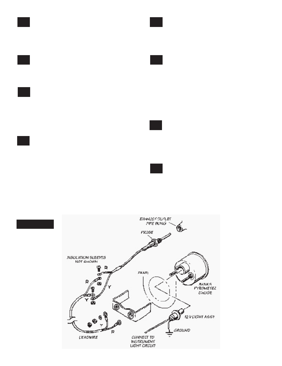
slide the protective sleeves over the longer
of each of the wire ends on the probe and
the leadwire. connect the longer red leadwire to
the red thermocouple wire and the shorter yellow
leadwire to the yellow thermocouple wire with the
screws and nuts provided. See figure
7
.
24.
locate a position on the firewall where a
3
⁄
8
”
hole can be drilled that will not interfere with
anything on either side of the firewall. pay special
attention to any wiring on the interior of the vehicle.
drill and deburr the hole.
25.
route the leadwire across the engine bay
and through the hole in the firewall. from
inside the vehicle route the leadwire to the gauge
head location. coil any excess leadwire either
under the hood or under the dash. DO NOT
SHORTEN THE LEADWIRE. The pyrometer is
calibrated for the specific length of leadwire
provided.
26.
remove the jumper wire from the terminals
on the back of the pyrometer gauge. insert
the pyrometer gauge through the panel, then slide
the u-clamp over the terminal studs. connect the
leadwire to the pyrometer, making sure that the
yellow wire is connected to the positive (+)
terminal and the red wire is connected to the
other terminal. use double nuts and lockwashers
provided to attach the leadwire to each stud and
tighten the gauge in the panel. do not loosen the
nuts that are already on the pyrometer gauge
terminal studs.
27.
install one end of the
1
⁄
8
” diameter plastic
tube provided into the nut and ferrule fitting
earlier installed in the intake plenum and tighten
the nut. be sure that the plastic tube cannot be
pulled out of the ferrule, but do not overtighten
the nut.
28.
route the plastic tube toward the firewall
and insert the tube through the hole
previously drilled. Make sure that the pyrometer
leadwire and the boost hose will not be chaffed
by the edge of the drilled hole. it may be
necessary to install a rubber grommet or use
silicone to seal the hole. route the tube toward
the gauge panel and cut to the proper length.
install the gauge with the hardware provided.
install the tube into the remaining fitting provided
at the back of the boost gauge.
29.
connect one wire from each gauge light to
a good ground location under the dash,
such as a metal support bracket where other
wires may already be grounded. connect the
remaining light wires together and to an 18 gauge
or larger wire, connected to either the headlight
circuit or the dash lighting circuit.
30.
reconnect the batteries. start the engine
and allow it to warm up. drive the vehicle
and listen for exhaust leaks or rattles. reposition
or tighten exhaust components as required. Tack
welds at each exhaust slip joint are recommended.
note: The exhaust system may smoke somewhat
at first as the grease used in the bending process
burns off the inside of the pipes.
figure 7
10
p.n. 96309 v.3.0
23.