Banks Power Ford Trucks: (Diesel ’99 - 03 7.3L Power Stroke) Power Systems- Stinger, Stinger-Plus & PowerPack systems '19991_2-2003 F250_F350 Trucks & Excursion (non-cat) User Manual
Page 8
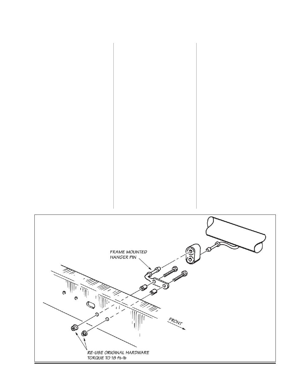
21.
On the 2002-03 F-series
models only, it is necessary to
relocate the factory-installed
frame-mounted hanger pin that is
located behind the transmission
crossmember.
A. Remove the two (2) nuts that hold
the frame-mounted hanger pin to
the frame rail, save for reinstallation
later. Remove the frame-mounted
hanger pin from vehicle.
B. Remove the two (2) 8mm studs
from the frame-mount hanger pin.
C. Reinstall the frame-mounted
hanger pin using the two (2)
5
⁄
8
” long
steel spacers, two (2) 8mm x 1.25 x
45mm bolts and the two (2) 8mm nuts
(removed in Step A above). See Figure
3 for proper assembly sequence.
Torque fasteners to 18 ft-lb.
22.
Reusing the saved V-band clamp
previously put aside, loosely clamp
the upper portion of the turbine
outlet pipe to the warm-up valve or
the Banks Brake on the turbocharger.
Do not tighten at this time.
23.
Place a 4” exhaust clamp on the
turbine outlet pipe. Install the front
intermediate pipe onto the turbine
outlet pipe. Place a 4” exhaust clamp
on the front intermediate pipe (see
Figure 5).
24.
For Standard Cab long-bed
vehicles: It will be necessary to cut
43
⁄
4
” off the rear intermediate pipe
supplied in the kit. The hanger will
be removed with the unused portion
of the pipe (see Figure 4). Install the
rear intermediate pipe.
Install the rear intermediate pipe as
supplied (no cut required).
Install the rear intermediate pipe.
Place a 4” clamp on the end of the
rear intermediate pipe and install the
extension pipe (P/N 53513).
Remove the rear frame mounted
hanger and install the supplied frame
mounted hanger in its place, using
the two 8mm x 30mm hex bolts
supplied and re-using the two 8mm
nuts previously removed (see Figure
6). Install the rear intermediate pipe.
Place a 4” clamp on the end of the
rear intermediate pipe and install the
extension pipe (P/N 53514).
Install the rear intermediate pipe.
Place a 4” clamp on the end of the
ear intermediate pipe and install the
extension pipe (P/N 53515).
25.
If installing a Git-Kit, place a 3
1
⁄
2
”
clamp on the adapter provided and
install it on the stock intermediate or
extension pipe.
26.
Place the front hanger clamp
on the inlet end of the Banks
Monster muffler and install it onto
the intermediate pipe or extension
pipe. Note the inlet labeling on the
Monster muffler. Be sure the Banks
Monster embossing on the muffler is
level with the frame.
Insert the front hanger pin into the
rubber hanger at the front of the
muffler.
27.
slide the rear hanger clamp over
the outlet of the muffler with the
hanger pins facing forward. Insert the
hanger pin(s) into the corresponding
rubber hanger(s).
install a 4” clamp onto the muffler
outlet.
Install the Banks Monster tailpipe
over the rear axle housing and into
the outlet of the Monster muffler.
28.
Slip the 5” Monster tailpipe tip
on with the drain hole facing down
and Banks logo facing up. Keep the
wrapping on for now. For a Fleet-
side truck the 5” tip should be hung
1” past the end of the tailpipe. For
a dually, the tip should be 3
1
⁄
2
” past
the end of the tail pipe. Snug up the
clamp.
Section 4
ExHAuST INSTALLATION (PART 2 OF 2)
Figure 3
8
96334 v.5.0