Banks Power Ford Trucks: (Diesel ’94 - 97 7.3L Power Stroke) Power Systems- PowerPack, Stinger-Plus & Stinger '94-98 3-1_2" Exhaust User Manual
Page 7
Loosen the four clamps on the compressor
discharge plenum hoses and the clamp
attaching the plenum to the compressor. Pull the
compressor discharge plenum up off the engine.
Remove the O-ring that seals the compressor
outlet to the plenum.
At the rear of the turbine housing, remove
the two bolts at the top and the two nuts
at the bottom attaching the turbine housing to
the turbine inlet adapter.
See Figure 2
. Save the
turbine inlet gasket for reuse.
Unplug the electrical connector at the
driver-side of the compressor housing.
The turbocharger pedestal mount must be
removed with the turbocharger. Remove
the four bolts attaching the pedestal mount to the
engine block. The front two are easily accessible.
The rear two will require the use of a swivel
socket or a universal joint-socket combination.
After these bolts have been removed, lift the
assembly off of the engine towards the front.
Remove the two O-rings located on the engine or
under the pedestal mount.
Clamp the turbocharger assembly in a vise.
Do not use the compressor inlet or outlet to
clamp the turbocharger. The compressor housing
is aluminum and could be damaged. Observe and
mark the relationship of the exhaust backpressure
control valve to the turbine housing and the
turbine housing to the center section of the turbo
assembly.
Remove the exhaust backpressure control
valve from the turbine housing, and install
it onto the new turbine housing with the original
hardware. Duplicate the orientation of the original
assembly. Use anti-seize on the bolts.
Remove the four bolts securing the turbine
housing to the turbocharger center section.
If the turbocharger is more than a few months old,
it may be necessary to spray some Liquid Wrench
(or similar rust penetrating lubricant) into the
joint between the turbine housing and the center
section. Work the housing loose from the center
section by tapping with a hammer and brass drift
or a soft face hammer. Work from side to side and
use plenty of lubricant until the housing is loose
from the center section. Pull the housing straight
off of the center section to avoid damaging the
turbine blades.
Place Banks Quick-Turbo
®
turbine housing
onto the center section, again paying careful
attention to the turbine blades. Apply some anti-
seize to the four bolts and reinstall them. Check
the orientation of the assembly, then tighten the
bolts.
Make sure the gasket is on the turbine
inlet adapter on the engine. Place the new
O-rings provided into the recesses on the engine
block and make sure that the sealing area of the
pedestal bottom is clean.
Î
Reinstall the turbocharger and pedestal
assembly. Make sure the O-rings are in
place before installing any bolts. Put a small
amount of anti-seize on the turbine inlet bolts
and nuts and start them. Install and tighten the
pedestal mounting bolts then tighten the turbine
inlet bolts and nuts. Plug the electrical connector
back together.
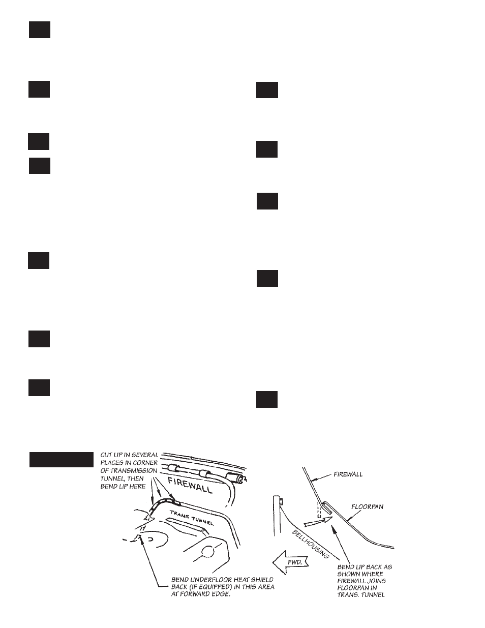
Bend the firewall lip seam as far back as
possible, on the right side corner of the
transmission tunnel, to allow for installation of
Banks two-piece turbine outlet pipe. A 3-4 foot
piece of pipe or heavy metal bar may be used as
a lever and extended hammer to fold and flatten
the seam against the floorpan. NOTE: If access to
a Sawzall or an air chisel is available, a series of
cuts in the seam will ease the bending operation.
It may also be necessary to somewhat compress
and reshape the floorpan heatshield behind the
firewall lip seam using a pipe or heavy prybar.
See
Figure 3.
Reinstall the dipstick tube, dipstick and
cooler line if removed. Be sure to connect
the electrical ground between the cylinder head
and dipstick mount on the passenger-side.
27.
26.
25.
24.
23.
22.
21.
20.
19.
18.
17.
16.
FIGURE 3
7
P.N. 96322 v.7.0