Banks Power Ford Trucks: (Diesel ’94 - 97 7.3L Power Stroke) Power Systems- PowerPack, Stinger-Plus & Stinger '94-98 3-1_2" Exhaust User Manual
Page 17
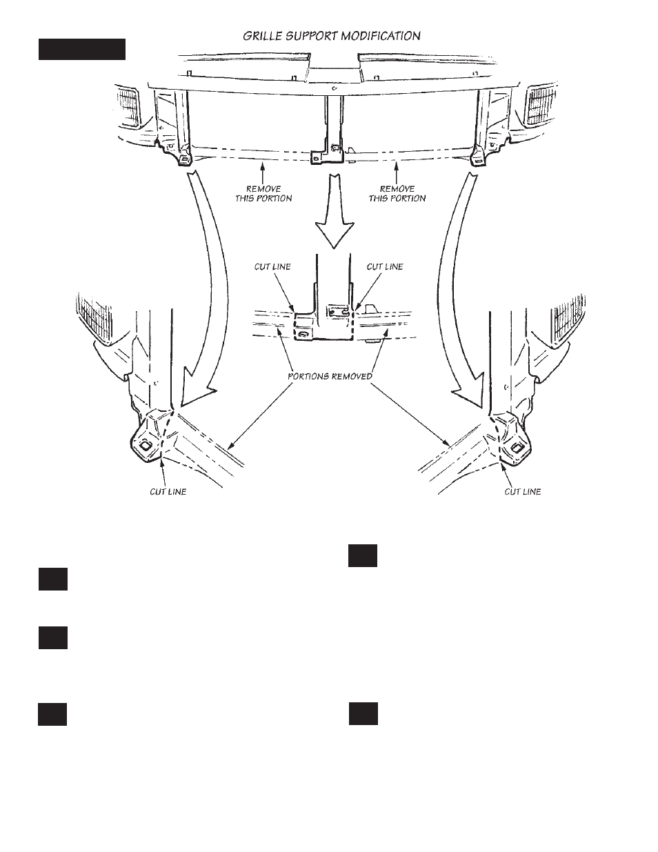
FIGURE 14
and puncture a tube in the intercooler core. There
should be a minimum of
1
⁄
4
-inch clearance between
the end of the screw and the intercooler core. If
necessary, shorten the screw.
Reinstall the headlight bezels. Be sure that
the lights are in the correct locations. If
in doubt, turn on the hazard flashers. The turn
signals will be the flashing ones.
Reinstall the grille against the grille support
with the original hardware. Reinstall the
front bumper onto the stud plates and tighten
the nuts. Once again, check the tightness of all
hose clamps to ensure the integrity of the hose
connections at high boost levels.
Clean an area that is easily visible on the
upper radiator core support with a non-oil
based solvent, such as Acetone, Mineral Spirits,
Denatured Alcohol or Lacquer Thinner. Allow to
dry and then attach the Banks E.O. sticker to the
upper radiator core support.
DYNAFACT INSTRUMENTATION INSTALLATION
GAUGE PANEL
If the gauges are being installed into an
existing gauge panel, this step may be
skipped. If gauges and a gauge panel are being
installed, choose a location where the gauges can
be easily viewed by the driver. This will typically
be to the right of the accelerator pedal, under the
lower edge of the dash panel. Mount the gauge
panel with the machine screws, washers, and
nuts provided. NOTE: Molded instrument panels
for top of dash mounting are available from Gale
Banks Engineering.
DYNAFACT PYROMETER
Install the DynaFact
®
pyrometer probe
(supplied in the pyrometer kit) in the
1
⁄
4
-inch
NPT bung located at the top of the turbine outlet
pipe. Use anti-seize compound on the threads.
Connect the lead-wire to the sensor with the
supplied screws. The wires are different lengths
to prevent cross connecting. Make sure that the
screws are tight. Slip the heat shrink tubing provided
over the wire ends.
72.
71.
70.
68.
69.
17
P.N. 96322 v.7.0