Installation instructions – Banks Power Ford Trucks: (Diesel ’94 - 97 7.3L Power Stroke) Power Systems- PowerPack, Stinger-Plus & Stinger '94-98 3-1_2" Exhaust User Manual
Page 5
INSTALLATION INSTRUCTIONS
Replace the stock air filter element with the
Banks Ram-Air filter.
Raise vehicle on a hoist or safety stands
to provide access to the exhaust system.
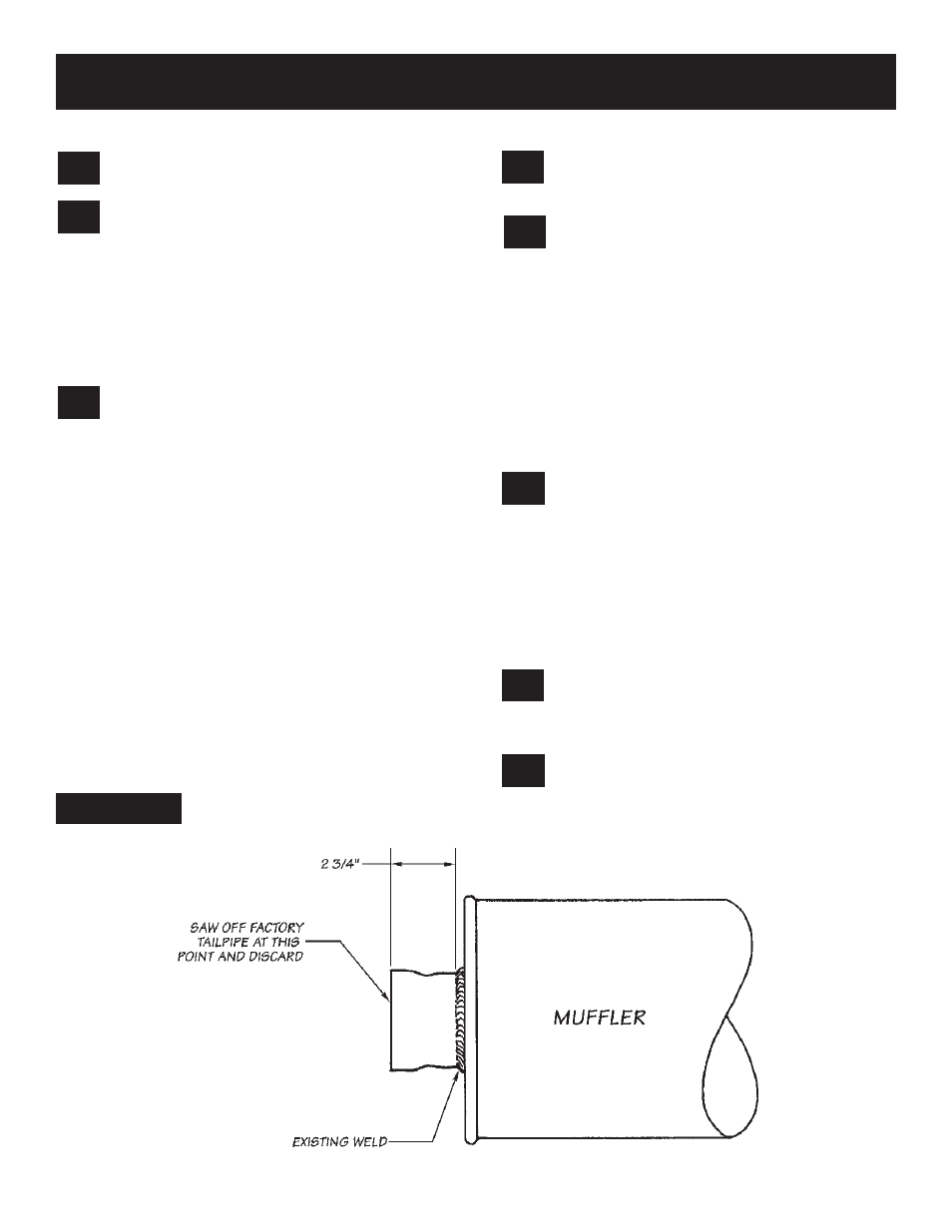
Mark a point 2
3
⁄
4
-inches from the rear-most edge
of the weld joining the tailpipe to the muffler. At
the mark, cut through the tailpipe square to the
muffler. Remove the tailpipe from the vehicle by
prying the pin from the hanger and pulling the
pipe rearward over the axle. De-burr the cut on
the tubing which remains attached to the muffler.
See Figure 1
.
Loosen the clamp at the outlet of the
catalytic converter. Unbolt the catalytic
converter from the turbine outlet pipe and
remove the converter from the vehicle. Heat from
a torch will most likely be required to separate
the converter slip joint. NOTE: It is very important
to inspect the catalytic converter. Diesel catalysts
may become plugged with soot and can cause
a restriction to exhaust flow. Performance may
be impeded if this is the case. Shine a powerful
flashlight into the slip joint end of the converter.
Observe the light through the other end of the
converter. The full circle of the flashlight should
be visible without any blockage in the grid work
of the catalyst. If excessive soot is observed,
the catalyst may need to be cleaned. TAKE
PRECAUTIONS to avoid blowing soot toward the
work area or where it could be inhaled. ALWAYS
use breathing protection. Also inspect the catalyst
for damage (i.e. chips, bent corners, etc.) to the
gridwork. If your catalytic converter is damaged,
it may be covered under your vehicles emissions
warranty.
Remove the decorative black cover directly
over the engine. Remove the engine lifting
hook at the rear of the right cylinder head.
AUTOMATIC TRANSMISSION ONLY
Remove the transmission dipstick and
unbolt the dipstick tube and engine ground wire
from the rear of the passenger-side cylinder head.
Pull the dipstick tube up out of the transmission.
Cover the dipstick tube opening with a rag or
paper towel to prevent contaminants from
entering the transmission. For additional
clearance, remove the transmission-fluid cooler
line that runs to the passenger-side of the
transmission, nearest the dipstick tube. DO NOT
start the vehicle while this line is disconnected,
as transmission fluid will quickly pump out of the
line.
Remove the V-clamp that secures
the factory turbine outlet pipe to the
turbocharger outlet. Pull the pipe up as far as
possible and cut the pipe as close to the engine
as possible. Discard the top section then remove
the bottom portion of the pipe from under the
vehicle.
For Stinger installations, proceed to Step 26.
TURBOCHARGER REMOVAL
Loosen the clamps holding the air intake
hose to the turbocharger compressor inlet
and the aluminum air intake casting. Remove the
hose.
See Figure 2
.
Disengage the exhaust backpressure control
actuator rod by sliding the cover on the
end of the rod back toward the turbocharger and
pulling the rod downward.
15.
14.
13.
12.
11.
10.
9.
8.
FIGURE 1
5
P.N. 96322 v.7.0