Figure 2, Cummins b5.9l – Banks Power Boost gauge User Manual
Page 4
4
p.n. 96327 v.3.0
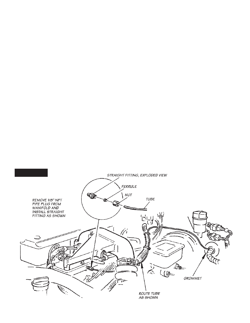
Ford/Navistar 6.9L/7.3L IDI diesel with Banks
Sidewinder turbo — locate the
1
⁄
8
" npT threaded hole
in the pressure chamber. install the straight fitting
provided into the threaded hole with teflon thread-
sealer.
Ford/Navistar 7.3L IDI diesel with factory turbo —
locate the
1
⁄
8
" npT pipe plug in the spiral pressure
chamber. remove the plug and install the straight
fitting provided into the threaded hole with Teflon
thread-sealer.
Ford/Navistar 7.3L Power Stroke diesel with factory
turbo — locate the rubber hose connecting the intake
manifold on the passenger-side of the engine to the
manifold pressure sensor mounted on the firewall. cut
through this hose at a point three inches below the
sensor.
install the plastic tee fitting and the spring band
clamps, provided, between the cut ends of the hose.
see figure 3.
install one 90-degree elbow fitting onto the threaded
end of the tee. sparingly apply Teflon thread-sealer to
the male pipe threads, and adjust the 90-degree elbow
fitting to point toward the firewall, as shown in
figure
3
. do not over-tighten the plastic fitting. do not allow
sealant to cover the small hole in the fitting.
tUbinG installation
all gauge tubing should be routed away from heat
sources such as exhaust manifolds or piping, and away
from sharp edges. avoid sharp bends or kinks. secure
the tubing to other tubing inside the engine
compartment with cable ties.
When passing through the firewall, either make a hole
in a factory grommet or drill a hole and use a new
grommet. if a hole needs to be drilled, drill a
5
⁄
16
" hole
and deburr it on both sides, so that the tubing does not
get cut as it passes through the hole. For added
protection, wrap the tubing with several layers of
electrical tape in the area where it passes through the
hole. When drilling, check the backside to make sure
that there are no components blocking the back side of
the hole that would be damaged by drilling.
install one end of the
1
⁄
8
" diameter plastic tube,
provided, in the nut and ferrule on the adapter fitting,
and tighten the nut. check that the plastic tube cannot
be pulled out of the ferrule. do not over-tighten the nut.
route the plastic tube toward the firewall.
NOTE: If the boost gauge appears to stick after
installation, trim about
1
⁄
2
" from each end of the plastic
tube and reinstall, being careful not to over-tighten.
FIGURE 2
cUmmins b5.9l