Installation procedure, Figure 1, Chevrolet/gmc 6.5l – Banks Power Boost gauge User Manual
Page 3
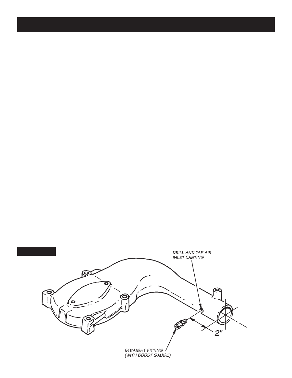
FIGURE 1
GaUGE PanEl installation
choose a suitable location under the lower edge of the
dash panel for mounting the instrument panel, or on
top of the dash for the molded instrument console. be
certain the instruments can be viewed conveniently by
the driver.
under dasH — using the panel as a template,
drill
two
3
⁄
16
" diameter holes in the dash and mount the
panel with two 10 x
1
⁄
2
" machine screws, nuts, and
star-washers provided.
On TOp OF dasH — Wipe the dash-top with an alcohol
pad or other surface cleaner. remove the backing from
the adhesive Velcro tape on the bottom of the console
adapter, position the console adapter and press down
firmly. Once the gauges are wired and secured to the
console according to the following instructions, attach
the console assembly to the console adapter using the
two machine screws provided.
boost GaUGE adaPtEr fittinG location
boost levels vary widely, depending on the engine and
turbocharger configuration. refer to the Owners
Manual for your banks system to determine maximum
boost specifications for your specific application.
Chevrolet/GMC 6.2L/6.5L diesel with Banks
Sidewinder turbo — locate the
1
⁄
8
" npT threaded hole
in the pressure chamber. install the straight fitting
provided into the threaded hole with teflon thread-
sealer.
Chevrolet/GMC 6.5L diesel with factory turbo —
loosen the hose clamp on the compressor discharge
of the turbocharger. remove the connecting strap
between turbocharger and air inlet casting.
unbolt and remove the air inlet casting from the top of
intake manifold. warninG! foreign matter in the
intake manifold can cause serious engine and/or
turbocharger damage upon engine start-up.
cover the intake manifold opening to prevent foreign
objects or debris from falling into engine.
Measure and mark the air inlet casting as shown in
figure 1
. center-punch this location and drill through
the casting wall with a 0.399-diameter letter r drill. Tap
the hole with a
1
⁄
8
" npT tap. clean all chips from inside
the casting.
use of a new gasket is recommend for reinstallation of
the air inlet casting on intake manifold. Tighten loose
clamps and reinstall the brace. install straight fitting,
supplied, into hole tapped in air inlet casting. use a
Teflon thread-sealer on fitting pipe threads.
Cummins B5.9L/C8.3L diesel with factory turbo —
locate and remove the
1
⁄
8
" npT pipe plug on the side of
the intake manifold as shown in
figure 2
. NOTE: In
Dodge pickups this plug is on the driver-side. In pusher
motorhomes, it is on the passenger-side. install the
straight fitting at this location, using Teflon thread-
sealer on the pipe thread end of the adapter fitting. On
some cummins c8.3l applications, it may be necessary
to remove a
1
⁄
2
" npT pipe plug from the inlet casting
and install a reducer bushing.
INSTALLATION PROCEDURE
3
p.n. 96327 v.3.0
chEVrolEt/Gmc 6.5l