Playback, Search, Push video configuration – Velleman DVR8H2 Quick Installation Guide User Manual
Page 9: 1 pin connection
DVR8H2
V. 02 – 07/01/2014
9
©Velleman nv
o
If timer recording is enabled, the timer recording icon (
) is displayed.
o
By default, the device is in HDD overwrite mode and the icon (
) is displayed.
Playback
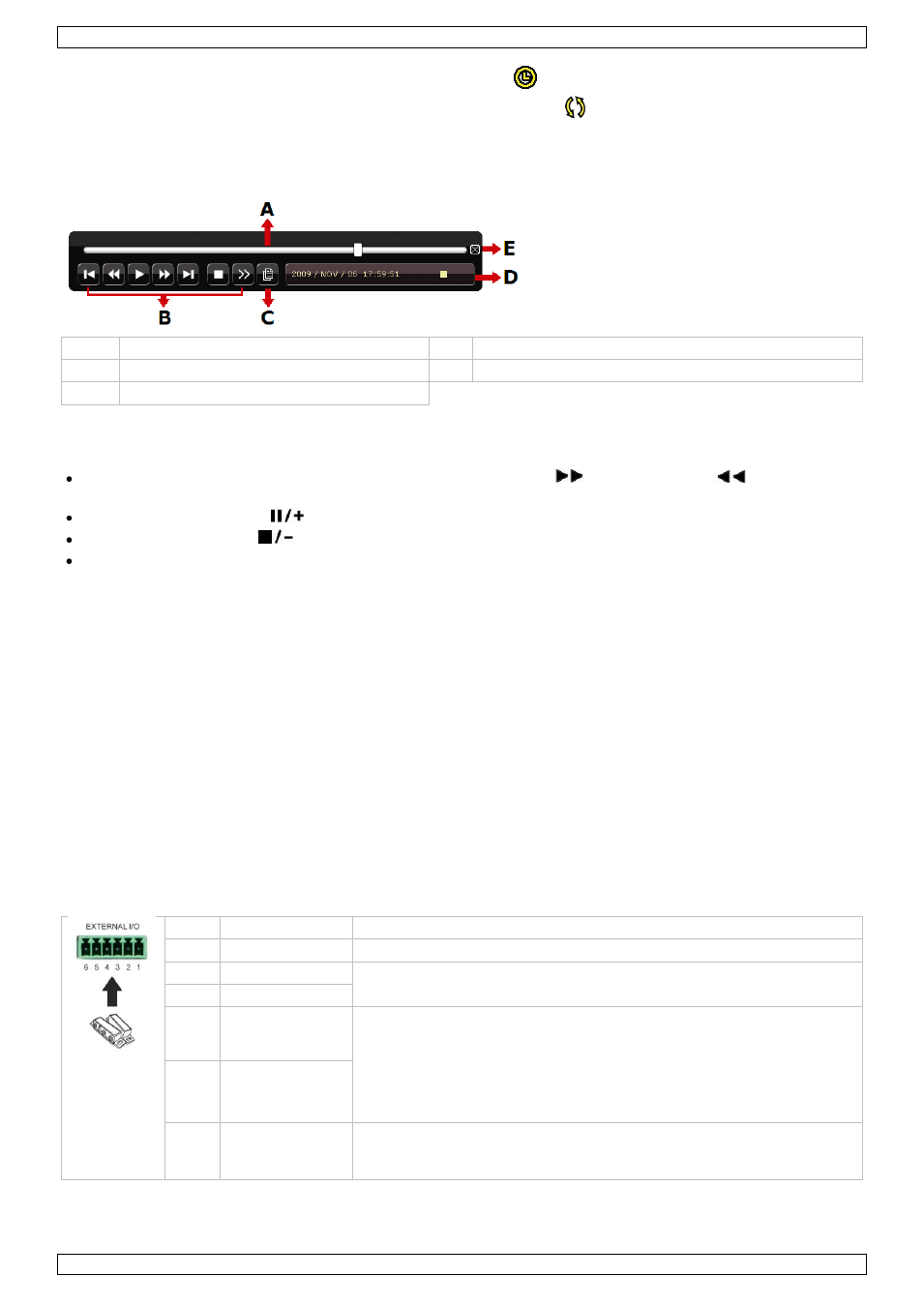
Make sure the control panel is not locked and press the PLAY button on the control panel or use the quick menu
bar to open the playback control panel:
A
progress bar
D information bar
B
control bar
E
close
C
event search
Note: There must be at least 8192 images of recorded data for playback to work properly. If not, the device
will stop playback. For example, if the IPS is 30, the recording time should be at least 273 seconds
(8192 images / 30 IPS) for the playback to work properly.
Increase or decrease the playback speed using the fast forward (
) and fast rewind (
) buttons. Click
once to get 4x speed forward/backward, click twice to get 8x speed, etc. Maximum speed is 32x.
Press the pause button (
) to pause playback.
Press the stop button (
) to return to live monitoring.
Press the SLOW button once to get 1/4x speed playback, and click twice to get 1/8x speed playback.
Search
There are four ways to search recorded files: by record list, motion list, alarm list or by timer list.
1. To search an event, press the LIST button on the front panel (make sure the control panel is not locked).
An overview of the recorded file types (ALARM, MANUAL, MOTION, SYSTEM and FULL LIST) is shown.
2. Select the desired list and recording from the list.
3. Press ENTER to start playback.
Note: The recorded files can also be searched via the included Video Viewer software.
9.
Push Video Configuration
9.1
Pin Connection
This DVR can send notifications and video to your mobile devices, such as iPhone, iPad, and Android mobile
devices, when an alarm event occurs (push video).
For alarm triggering, you can use the camera on input channel 1 together with an external alarm sensor (such
as a magnetic contact) via the external I/O block on the DVR rear panel.
Refer to the table below for an overview of the pin connections of the external I/O block.
Pin
Function
Description
1
GND
Ground
2
RS-485-A
For PTZ camera control
3
RS-485-B
4
External alarm,
COM
Connect an external device such as a buzzer or siren between the
COM and NO pins. These pins function as a switch (normal open).
In normal operation, there is no connection between COM and NO
(switch is open). When an alarm is triggered, COM connects with NO
(switch is closed).
Attention: Max. voltage and current are 24 VDC, 1 A.
5
External alarm,
NO
6
Alarm input
Alarm-in for push video. Connect an alarm sensor between pin 1
(GND) and pin 6. When the sensor triggers an alarm, the DVR starts
recording from the camera connected to channel 1.