6f(r) series, Vishay high power products, Standard recovery diodes (stud version), 6 a – C&H Technology 6F10 User Manual
Page 4: Conduction
Document Number: 93519
For technical questions, contact: [email protected]
www.vishay.com
Revision: 29-Sep-08
3
6F(R) Series
Standard Recovery Diodes
(Stud Version), 6 A
Vishay High Power Products
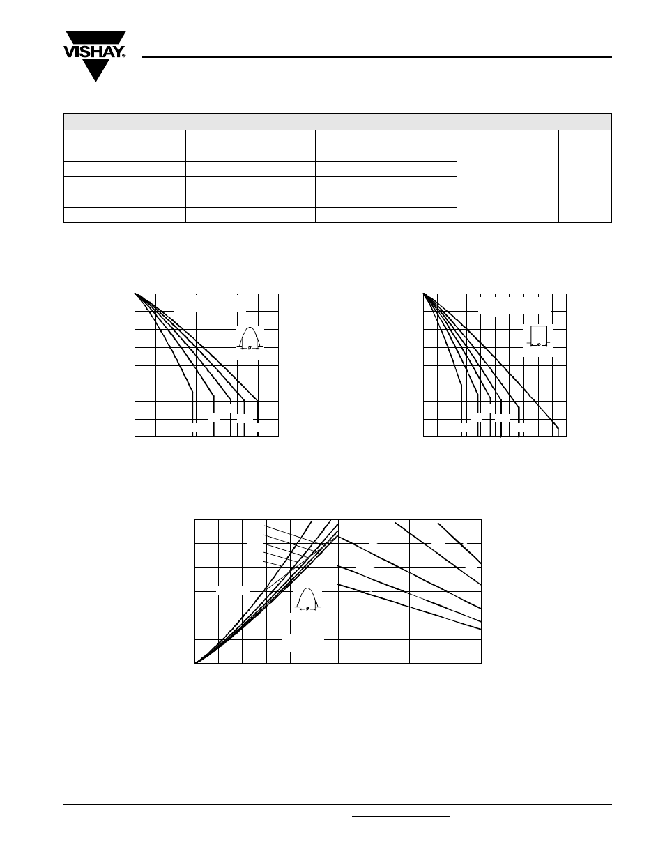
Note
• The table above shows the increment of thermal resistance R
thJC
when devices operate at different conduction angles than DC
Fig. 1 - Current Ratings Characteristics
Fig. 2 - Current Ratings Characteristics
Fig. 3 - Forward Power Loss Characteristics
ΔR
thJC
CONDUCTION
CONDUCTION ANGLE
SINUSOIDAL CONDUCTION
RECTANGULAR CONDUCTION
TEST CONDITIONS
UNITS
180°
0.34
0.29
T
J
= T
J
maximum
K/W
120°
0.44
0.48
90°
0.57
0.63
60°
0.85
0.88
30°
1.37
1.39
155
160
165
170
175
0
1
2
3
4
5
6
7
30°
60°
90°
120°
180°
Ma
xi
m
u
m A
llo
w
a
b
le
C
a
se
T
e
m
p
er
at
u
re
(
°C)
Conduction Angle
Average Forward Current (A)
6F(R) Series
R (DC) = 2.5 K/W
thJC
155
160
165
170
175
0
2
4
6
8
10
DC
30°
60°
90°
120°
180°
Ma
x
im
u
m A
llo
w
a
b
le
C
a
s
e
T
e
m
p
e
ra
tu
re
(
°C
)
Conduction Period
Average Forward Current (A)
6F(R) Series
R (DC) = 2.5 K/W
thJC
0
25
50
75
100
Maximum Allowable Ambient Temperature (°C)
15
K/W
R
=
20
K/W
- D
elta
R
th
SA
30
K/W
40 K/W
50 K/W
0
1
2
3
4
5
6
0
1
2
3
4
5
6
Average Forward Current (A)
RMS Limit
Ma
x
im
u
m A
ver
age
F
o
rw
ar
d
P
o
w
er
Lo
s
s
(
W
)
Conduction Angle
180°
120°
90°
60°
30°
6F(R) Series
T = 175°C
J