80ria...pbf/81ria...pbf series, Vishay high power products, Phase control thyristors (stud version), 80 a – C&H Technology 80RIA...PbF Series User Manual
Page 6
Document Number: 94392
For technical questions, contact: [email protected]
www.vishay.com
Revision: 30-Apr-08
5
80RIA...PbF/81RIA...PbF Series
Phase Control Thyristors
(Stud Version), 80 A
Vishay High Power Products
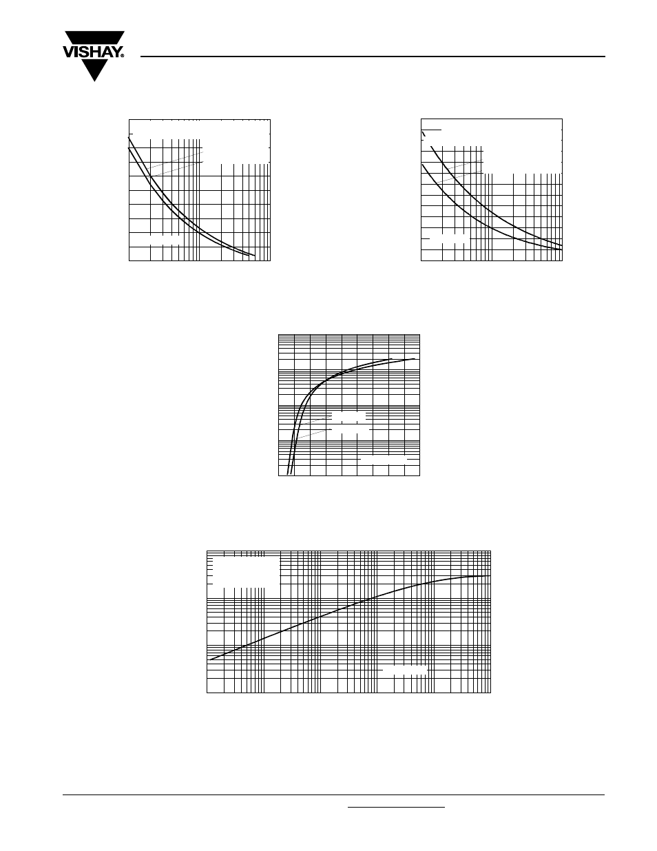
Fig. 5 - Maximum Non-Repetitive Surge Current
Fig. 6 - Maximum Non-Repetitive Surge Current
Fig. 7 - On-State Voltage Drop Characteristics
Fig. 8 - Thermal Impedance Z
thJC
Characteristics
800
1000
1200
1400
1600
1800
1
10
100
Number Of Eq ua l Amp litud e Half Cyc le Current Pulses (N)
P
e
a
k
H
a
lf
S
in
e
W
a
v
e
On
-s
ta
te
C
u
rr
e
n
t (
A
)
at 60 Hz 0.0083 s
at 50 Hz 0.0100 s
80RIA Series
At Any Rated Load Condition And With
Rated V Applied Following Surge.
RRM
Initial T
J
= 125°C
700
800
900
1000
1100
1200
1300
1400
1500
1600
1700
1800
1900
2000
0.01
0.1
1
Pulse Train Duration (s)
Versus Pulse Train Duration. Control
Of Conduction May Not Be Maintained.
P
e
a
k
H
a
lf
S
in
e
W
a
v
e
O
n
-s
ta
te C
u
rr
e
n
t (
A
)
Initial T = 125°C
No Voltage Reapplied
Rated V Reapplied
RRM
J
80RIA Series
Maximum Non Repetitive Surge Current
1
10
100
1000
10000
0.5
1
1.5
2
2.5
3
3.5
4
4.5
5
T = 25°C
J
In
st
an
ta
ne
ou
s O
n
-s
ta
te
C
u
rr
e
n
t (
A
)
Instantaneous On-state Voltage (V)
T = 125°C
J
80RIA Series
0.001
0.01
0.1
1
0.0001
0.001
0.01
0.1
1
10
Sq uare Wave Pulse Duration (s)
th
J
C
80RIA Series
Steady State Value
R = 0.30 K/W
(DC Operation)
Tr
an
si
e
n
t T
h
e
rm
a
l I
m
pe
da
n
c
e
Z
(K
/W
)
thJC