10ets...pbf high voltage series, Vishay high power products, Input rectifier diode, 10 a – C&H Technology 10ETS...PbF High Voltage Series User Manual
Page 4
Document Number: 94337
For technical questions, contact: [email protected]
www.vishay.com
Revision: 19-Mar-08
3
10ETS...PbF High Voltage Series
Input Rectifier Diode, 10 A
Vishay High Power Products
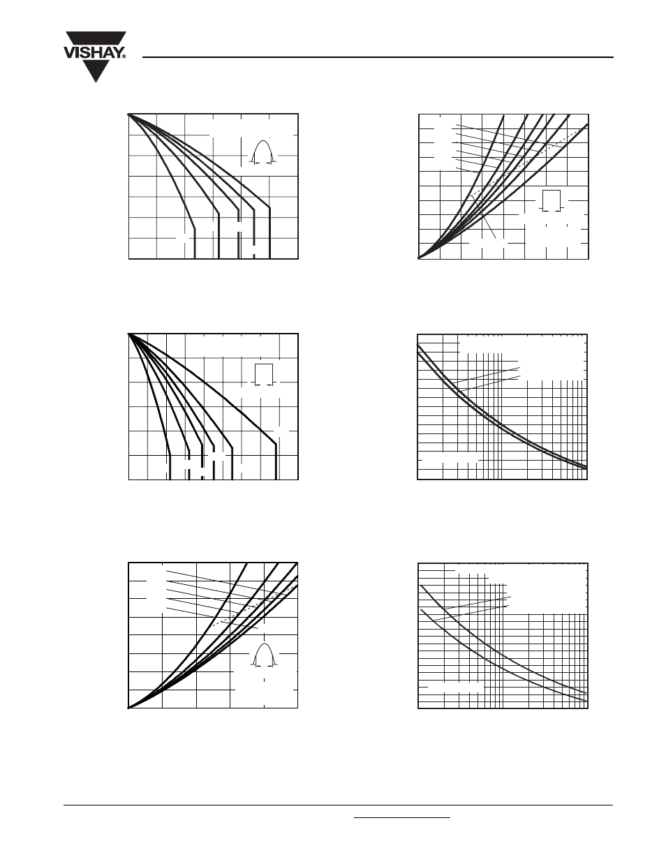
Fig. 1 - Current Rating Characteristics
Fig. 2 - Current Rating Characteristics
Fig. 3 - Forward Power Loss Characteristics
Fig. 4 - Forward Power Loss Characteristics
Fig. 5 - Maximum Non-Repetitive Surge Current
Fig. 6 - Maximum Non-Repetitve Surge Current
80
90
110
100
140
150
130
120
Maximum Allowable
Case Temperature (°C)
Average Forward Current (A)
2
10
12
4
6
8
0
30°
60°
90°
120°
180°
10ETS.. Series
R
thJC
(DC) = 2.5 °C/W
Conduction angle
Ø
90
150
140
130
120
110
100
4
2
6
8
16
18
10
12
14
0
Maximum Allowable
Case Temperature (°C)
Average Forward Current (A)
DC
30°
60°
90°
120°
180°
10ETS.. Series
R
thJC
(DC) = 2.5 °C/W
Ø
Conduction period
8
2
0
4
6
10
14
12
16
Maximum Average
Forward Power Loss (W)
Average Forward Current (A)
2
4
6
8
10
0
180°
120°
90°
60°
30°
Conduction angle
Ø
10ETS.. Series
T
J
= 150 °C
RMS limit
0
2
4
6
8
10
12
14
16
18
20
16
14
12
10
0
2
4
6
8
Maximum Average
Forward Power Loss (W)
Average Forward Current (A)
DC
180°
120°
90°
60°
30°
RMS limit
10ETS.. Series
T
J
= 150 °C
Ø
Conduction period
100
120
140
160
180
200
80
40
60
Peak Half Sine Wave
Forward Current (A)
Number of Equal Amplitude
Half Cycle Current Pulses (N)
10
100
1
Initial T
J
= 150 °C
at 60 Hz 0.0083 s
at 50 Hz 0.0100 s
10ETS.. Series
At any rated load condition and with
rated V
RRM
applied following surge.
200
100
120
140
160
180
220
240
40
60
80
0.1
1.0
0.01
Peak Half Sine Wave
Forward Current (A)
Pulse Train Duration (s)
10ETS.. Series
Maximum non-repetitive surge current
versus pulse train duration.
Initial T
J
= 150 °C
No voltage reapplied
Rated V
RRM
reapplied