200hf..l, Vishay high power products, Standard recovery diodes (stud version), 200 a – C&H Technology 200HF..L Series User Manual
Page 3
www.vishay.com
For technical questions, contact: [email protected]
Document Number: 93500
2
Revision: 28-May-08
200HF..L
Vishay High Power Products
Standard Recovery Diodes
(Stud Version), 200 A
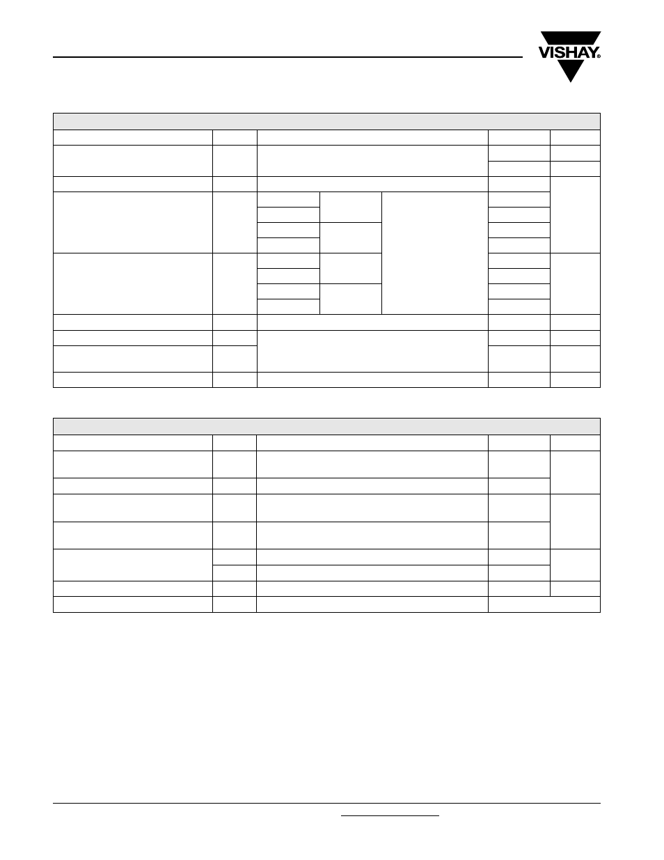
FORWARD CONDUCTION
PARAMETER
SYMBOL
TEST CONDITIONS
VALUES
UNITS
Maximum average forward current
at case temperature
I
F(AV)
180° conduction, half sine wave
200
A
125
°C
Maximum RMS forward current
I
F(RMS)
DC at 115 °C case temperature
314
A
Maximum peak, one cycle forward,
non-repetitive surge current
I
FSM
t = 10 ms
No voltage
reapplied
Sinusoidal half wave,
initial T
J
= T
J
maximum
3570
t = 8.3 ms
3740
t = 10 ms
100 % V
RRM
reapplied
3000
t = 8.3 ms
3140
Maximum I
2
t for fusing
I
2
t
t = 10 ms
No voltage
reapplied
64
kA
2
s
t = 8.3 ms
58
t = 10 ms
100 % V
RRM
reapplied
45
t = 8.3 ms
41
Maximum I
2
√t for fusing
I
2
√t
t = 0.1 to 10 ms, no voltage reapplied
640
kA
2
√s
Low level value of threshold voltage
V
F(TO)1
(16.7 % x
π x I
F(AV)
< I <
π x I
F(AV)
), T
J
= T
J
maximum
0.73
V
Low level value of forward
slope resistance
r
f1
0.48
m
Ω
Maximum forward voltage drop
V
FM
I
pk
= 628 A, T
J
= 25 °C
1.12
V
THERMAL AND MECHANICAL SPECIFICATIONS
PARAMETER SYMBOL
TEST
CONDITIONS
VALUES
UNITS
Maximum junction operating
temperature range
T
J
- 40 to 180
°C
Maximum storage temperature range
T
Stg
- 55 to 180
Maximum thermal resistance,
junction to case
R
thJC
DC operation
0.25
K/W
Maximum thermal resistance,
case to heatsink
R
thCS
Mounting surface, smooth, flat and greased
0.08
Maximum allowed mounting torque
+ 0 - 20 %
Not lubricated threads
11
N · m
lubricated threads
10
Approximate weight
120
g
Case style
See dimensions - link at the end of datasheet
DO-205AC (DO-30)