No t for ne w de sig n, Vishay roederstein – C&H Technology EYV User Manual
Page 2
NO
T
FOR
NE
W DE
SIG
N
www.vishay.com
For technical questions, contact: [email protected]
Document Number: 25126
2
Revision: 21-Aug-08
EYV
Vishay Roederstein
Aluminum Capacitors
Power Printed Wiring Style
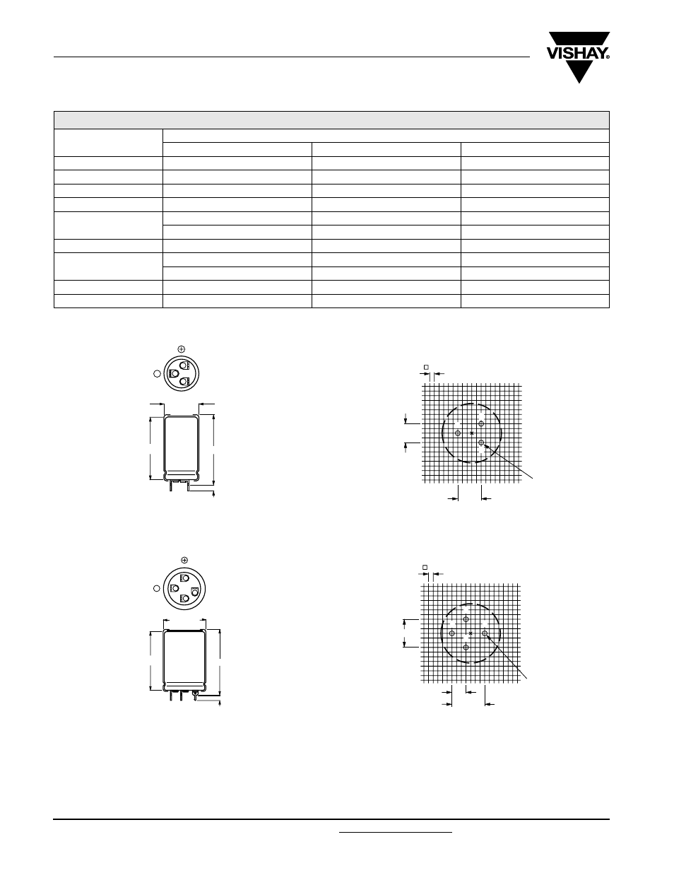
DIMENSIONS in millimeters AND AVAILABLE FORMS
Fig.1 Printed wiring pin version
Fig.2 Mounting hole pattern viewed from the component side
Fig.3 Printed wiring pin version
Fig.4 Mounting hole pattern viewed from the component side
SELECTION CHART FOR C
R
, U
R
AND RELEVANT NOMINAL CASE SIZES (Ø D x L in mm)
C
R
(µF)
U
R
(V)
250
385
400
47
-
25 x 30
25 x 30
68
-
25 x 40
25 x 40
100
25 x 30
30 x 40
30 x 40
150
25 x 40
35 x 40
35 x 40
220
30 x 40
35 x 50
35 x 50
-
40 x 40
40 x 40
330
35 x 40
40 x 50
40 x 50
470
35 x 50
40 x 70
40 x 70
40 x 40
-
-
680
40 x 50
-
40 x 100
1000
40 x 70
-
-
L
L + 5 max.
2
1
5
Ø D
+ 1 max.
-
5.1 ± 0.1
1 = Positive terminal
5 = Negative terminal
Case Ø D = 25 mm
Case Ø D = 25 mm
1.3
(3 x)
2.5
1
2
5
10 ± 0.1
12.5
± 0.1
1 = Positive terminal
5 = Negative terminal
Case Ø D = 30 mm and 35 mm
Ø D
+ 1 max.
L
12
3
5
-
L + 5 max.
5.1 ± 0.1
Case Ø D = 30 mm and 35 mm
15 ± 0.1
1.3
(4 x)
7.5 ± 0.1
17.5
± 0.1
2.5
1
2
3
5