Voltage ratings absolute maximum ratings, Electrical specifications, Thermal-mechanical specifications – C&H Technology 182NQ030PbF User Manual
Page 3
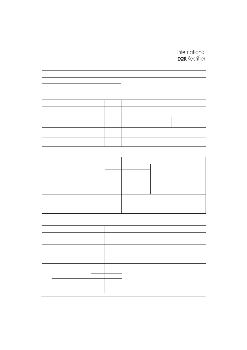
182NQ030PbF
Bulletin PD-21149
06/06
I
F(AV)
Max. Average Forward Current
180
A
50% duty cycle @ T
C
= 108 °C, rectangular wave form
* See Fig. 5
I
FSM
Max. Peak One Cycle Non-Repetitive
20000
5μs Sine or 3μs Rect. pulse
Surge Current * See Fig. 7
2500
10ms Sine or 6ms Rect. pulse
E
AS
Non-Repetitive Avalanche Energy
162
mJ
T
J
= 25 °C, I
AS
= 18 Amps, L = 1 mH
I
AR
Repetitive Avalanche Current
36
A
Current decaying linearly to zero in 1 μsec
Frequency limited by T
J
max. V
A
= 1.5 x V
R
typical
Part number
182NQ030PbF
V
R
Max. DC Reverse Voltage (V)
V
RWM
Max. Working Peak Reverse Voltage (V)
30
Voltage Ratings
Absolute Maximum Ratings
Following any rated
load condition and with
rated V
RRM
applied
Parameters
182NQ Units Conditions
A
(1) Pulse Width = 500μs
V
FM
Max. Forward Voltage Drop
0.59
V
@ 180A
* See Fig. 1
(1)
0.8
V
@ 360A
0.45
V
@ 180A
0.65
V
@ 360A
I
RM
Max. Reverse Leakage Current
15
mA
T
J
= 25 °C
* See Fig. 2
840
mA
T
J
= 125 °C
C
T
Max. Junction Capacitance
7700
pF
V
R
= 5V
DC
(test signal range 100Khz to 1Mhz) 25°C
L
S
Typical Series Inductance
6.0
nH
From top of terminal hole to mounting plane
dv/dt Max. Voltage Rate of Change
10000
V/ μs
(Rated V
R
)
T
J
= 25 °C
T
J
= 125 °C
V
R
= rated V
R
Parameters
182NQ Units
Conditions
Electrical Specifications
T
J
Max. Junction Temperature Range
-55 to 150
°C
T
stg
Max. Storage Temperature Range
-55 to 150
°C
R
thJC
Max. Thermal Resistance Junction
0.28
°C/W
DC operation
* See Fig. 4
to Case
R
thCS
Typical Thermal Resistance, Case to
0.05
°C/W
Mounting surface , smooth and greased
Heatsink
wt
Approximate Weight
30 (1.06)
g (oz.)
T
Mounting Torque
Min.
3 (26.5)
Non-lubricated threads
Max.
4 (35.4)
Terminal Torque
Min.
3.4 (30)
Max.
5 (44.2)
Case Style
HALF PAK Module
Thermal-Mechanical Specifications
Parameters
182NQ Units
Conditions
Nm
(Ibf-in)
Document Number: 94460
www.vishay.com
2