104 phl-st, Vishay bccomponents – C&H Technology 104 PHL-ST User Manual
Page 4
Document Number: 28389
For technical questions, contact: [email protected]
www.vishay.com
Revision: 31-Oct-08
185
104 PHL-ST
Aluminum Capacitors
Power High Ripple Current
Long Life Screw Terminals
Vishay BCcomponents
Table 1
Note
•
Unless otherwise specified, all electrical values in table 2 apply at
T
amb
= 20 °C, P = 86 kPa to 106 kPa, RH = 45 % to 75 %.
ORDERING EXAMPLE
Electrolytic capacitor 104 PHL-ST series
4700 µF/250 V; ± 20 %
Nominal case size: Ø 65 x 105 mm; ST version
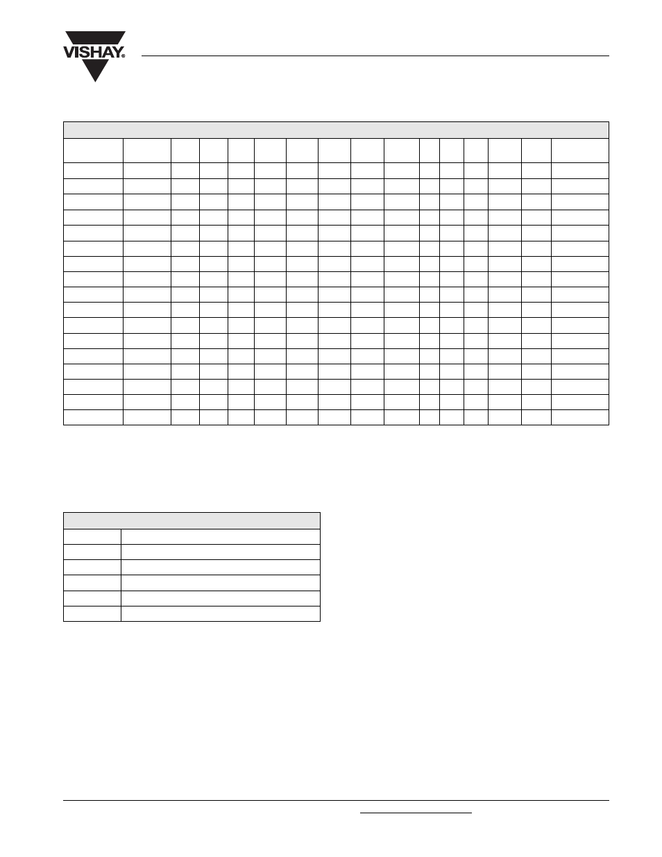
DIMENSIONS in millimeters, MASS AND PACKAGING QUANTITIES
DESIGN
DRAWING L ± 1 L
t
± 1 D ± 1 P ± 0.3 T ± 0.2 H ± 0.3 B ± 0.3 d
1
± 0.1
M
S - 0
Mb
l
b
± 0.1
MASS
(g)
PACKAGING
QUANTITIES
35 x 60
2A
63.3
68.7
35.3
12.8
7.0
4.6
11.0
7.9
M5
9.5
M8
12.0
75
50
35 x 80
2A
81.3
86.7
35.3
12.8
7.0
4.6
11.0
7.9
M5
9.5
M8
12.0
95
50
35 x 105
2A
103.3 108.7
35.3
12.8
7.0
4.6
11.0
7.9
M5
9.5
M8
12.0
130
50
50 x 80
2A
82.8
88.8
51.0
22.2
7.1
4.8
11.0
7.9
M5
9.5
M12
16.0
200
25
50 x 105
2A
104.8 110.8
51.0
22.2
7.1
4.8
11.0
7.9
M5
9.5
M12
16.0
300
25
65 x 105
2A
104.8 110.7
65.0
28.5
7.0
4.6
11.9
7.9
M5
9.5
M12
16.0
480
16
65 x 105 HC
2B
104.8 109.2
65.0
28.5
5.5
3.5
18.0
13.0
M6
8.5
M12
16.0
480
16
76 x 105
2A
105.8 111.7
76.4
31.8
7.0
4.6
11.7
7.9
M5
9.5
M12
16.0
700
12
76 x 105 HC
2B
105.8 110.2
76.4
31.8
5.5
3.5
18.3
13.0
M6
8.5
M12
16.0
700
12
76 x 114
2A
115.8 121.7
76.4
31.8
7.0
4.6
11.7
7.9
M5
9.5
M12
16.0
800
12
76 x 114 HC
2B
115.8 120.2
76.4
31.8
5.5
3.5
18.3
13.0
M6
8.5
M12
16.0
800
12
76 x 146
2A
145.8 151.7
76.4
31.8
7.0
4.6
11.7
7.9
M5
9.5
M12
16.0
1000
12
76 x 146 HC
2B
145.8 150.2
76.4
31.8
5.5
3.5
18.3
13.0
M6
8.5
M12
16.0
1000
12
76 x 220
2A
219.8 225.7
76.4
31.8
7.0
4.6
11.7
7.9
M5
9.5
M12
16.0
1500
10
76 x 220 HC
2B
219.8 224.2
76.4
31.8
5.5
3.5
18.3
13.0
M6
8.5
M12
16.0
1500
10
90 x 146 HC
2B
150.1 155.4
89.4
31.8
7.9
0.0
13.0
13.0
M6 10.0 M12
16.0
1300
10
90 x 220 HC
2B
218.1 223.4
89.4
31.8
7.9
0.0
13.0
13.0
M6 10.0 M12
16.0
2000
10
Note
• For bolt version holds:
1. L = L standard - 0.5 mm
2. L
t
= L
t
standard - 0.5 mm
ELECTRICAL DATA
SYMBOL
DESCRIPTION
C
R
rated capacitance at 100 Hz, tolerance ± 20 %
I
R
rated RMS ripple current at 100 Hz, 105 °C
I
L5
max. leakage current after 5 minutes at U
R
ESR
max. equivalent series resistance at 100 Hz
Z
impedance at 20 kHz
Ordering code: MAL2 104 13472 E3
Former 12NC:
2222 104 13472