Dual igbtmod™ a-series module – C&H Technology CM400DY-34A User Manual
Page 2
Dual IGBTMOD™
A-Series Module
400 Amperes/1700 Volts
CM400DY-34A
1
01/10 Rev. 1
Powerex, Inc., 173 Pavilion Lane, Youngwood, Pennsylvania 15697 (724) 925-7272
www.pwrx.com
Description:
Powerex IGBTMOD™ Modules
are designed for use in switching
applications. Each module
consists of two IGBT Transistors
in a half-bridge configuration with
each transistor having a reverse-
connected super-fast recovery
free-wheel diode. All components
and interconnects are isolated from
the heat sinking baseplate, offering
simplified system assembly and
thermal management.
Features:
£
Low Drive Power
£
Low VCE(sat)
£ Discrete Super-Fast Recovery
Free-Wheel Diode
£
Isolated Baseplate for Easy
Heat Sinking
Applications:
£
AC Motor Control
£
UPS
£
Battery Powered Supplies
Ordering Information:
Example: Select the complete
part module number you
desire from the table below -i.e.
CM400DY-34A is a 1700V (VCES),
400 Ampere Dual IGBTMOD™
Power Module.
Type
Current Rating
VCES
Amperes
Volts (x 50)
CM
400
34
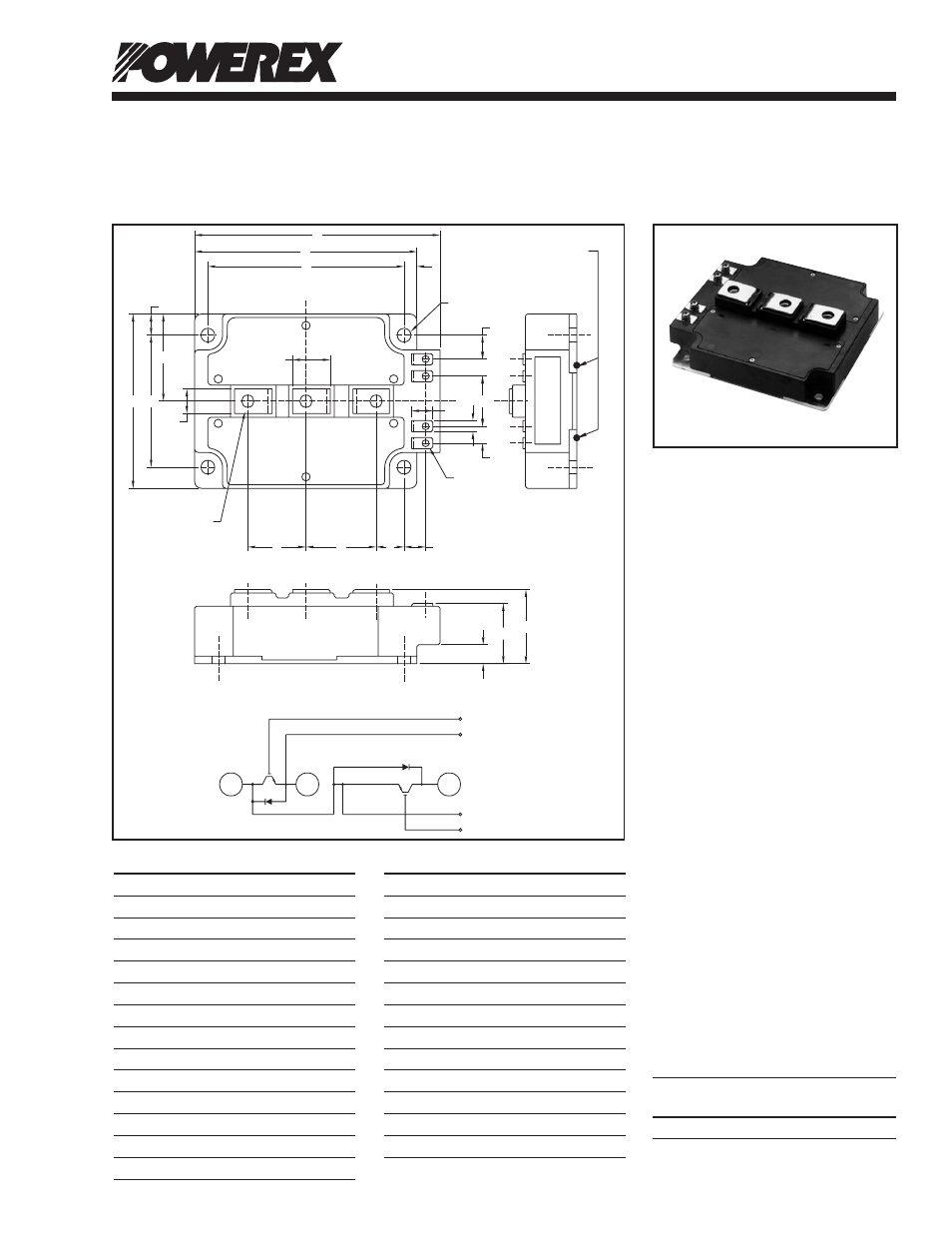
Dimensions
Inches
Millimeters
A
5.51
140.0
B
5.12
130.0
C
5.12
130.0
D
1.38+0.04/-0.02 35.0+1.0/-0.5
E
4.33+0.04/-0.02 110.0+1.0/-0.5
F
4.33+0.04/-0.02 110.0+1.0/-0.5
G
0.39
10.0
H
0.45
11.5
J
0.54
13.8
K
1.72
43.8
L
1.42
36.0
M
0.39
10.0
N
0.80
20.4
Dimensions
Inches
Millimeters
P
0.57
14.5
Q
1.57
40.0
R
2.56
65.0
S
M8
M8
T
0.26 Dia.
6.5 Dia.
S
0.32
8.0
V
0.97+0.04/-0.02 24.5+1.0/-0.5
W
M4
M4
X
0.59
15.0
Y
0.35
9.0
Z
1.02
26.0
AA
0.79
20.0
T - (4 TYP.)
C2E1
E2
G1
C1
E1
E2
G2
CL
L
C
W -
(4 PLACES)
LABEL
A
F
G
H
J
K
L
M
N
P
Q
P
R
U
V
D
X
Y
Z
C2E1
E2
C1
G1
E1
E2
G2
AA
TC MEASURED POINT
B
C E
S - (3 PLACES)
Outline Drawing and Circuit Diagram