40hf(r) series, Vishay high power products, Standard recovery diodes, (stud version), 40 a – C&H Technology 42HF(R) Series User Manual
Page 4
Document Number: 93513
For technical questions, contact: [email protected]
www.vishay.com
Revision: 23-Jun-08
3
40HF(R) Series
Standard Recovery Diodes,
(Stud Version), 40 A
Vishay High Power Products
Note
• The table above shows the increment of thermal resistance R
thJC
when devices operate at different conduction angles than DC
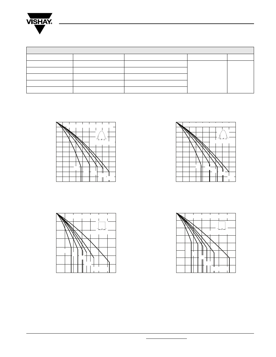
Fig. 1 - Current Ratings Characteristics
Fig. 2 - Current Ratings Characteristics
Fig. 3 - Current Ratings Characteristics
Fig. 4 - Current Ratings Characteristics
ΔR
thJC
CONDUCTION
CONDUCTION ANGLE
SINUSOIDAL CONDUCTION
RECTANGULAR CONDUCTION
TEST CONDITIONS
UNITS
180°
0.14
0.10
T
J
= T
J
maximum
K/W
120°
0.16
0.17
90°
0.21
0.22
60°
0.30
0.31
30°
0.50
0.50
Average Forward Current (A)
Maximum Allowable Case Temperature (°C)
130
140
150
160
170
180
190
0
5
10 15 20 25 30 35 40 45
30°
60°
90°
120°
180°
Conduction Angle
40HF(R) Series (100V to 1200V)
Average Forward Current (A)
Maximum Allowable Case Temperature (°C)
120
130
140
150
160
170
180
190
0
10
20
30
40
50
60
70
DC
30°
60°
90°
120°
180°
Conduction Period
40HF(R) Series (100V to 1200V)
Average Forward Current (A)
Maximum Allowable Case Temperature (°C)
100
110
120
130
140
150
160
0
5
10 15 20 25 30 35 40 45
30°
60°
90°
120°
180°
Conduction Angle
40HF(R) Series (1400V, 1600V)
Average Forward Current (A)
Maximum Allowable Case Temperature (°C)
80
90
100
110
120
130
140
150
160
0
10
20
30
40
50
60
70
DC
30°
60°
90°
120°
180°
Conduction Period
40HF(R) Series (1400V, 1600V)