160mt..kpbf series, Vishay high power products – C&H Technology 130-160MT..KPbF Series User Manual
Page 3
www.vishay.com
For technical questions, contact: [email protected]
Document Number: 94354
2
Revision: 29-Apr-08
130-160MT..KPbF Series
Vishay High Power Products
Three Phase Bridge, 130/160 A
(Power Modules)
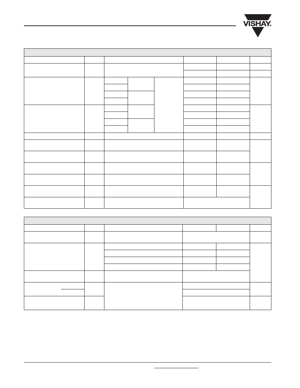
FORWARD CONDUCTION
PARAMETER
SYMBOL
TEST CONDITIONS
130MT.K
160MT.K
UNITS
Maximum DC output current
at case temperature
I
O
120° rect. conduction angle
130 (160)
160 (200)
A
85 (62)
85 (60)
°C
Maximum peak, one-cycle
forward, non-repetitive surge
current
I
TSM
t = 10 ms
No voltage
reapplied
Initial
T
J
= T
J
maximum
1130
1430
A
t = 8.3 ms
1180
1500
t = 10 ms
100 % V
RRM
reapplied
950
1200
t = 8.3 ms
1000
1260
Maximum I
2
t for fusing
I
2
t
t = 10 ms
No voltage
reapplied
64 000
102 000
A
2
s
t = 8.3 ms
5800
9300
t = 10 ms
100 % V
RRM
reapplied
4500
7200
t = 8.3 ms
4100
6600
Maximum I
2
√t for fusing
I
2
√t
t = 0.1 to 10 ms, no voltage reapplied
64 000
102 000
A
2
√s
Low level value of
threshold voltage
V
T(TO)1
(16.7 % x
π x I
T(AV)
< I <
π x I
T(AV)
),
T
J
maximum
0.78
0.81
V
High level value of
threshold voltage
V
T(TO)2
(I >
π x I
T(AV)
), T
J
maximum
0.99
1.04
Low level value of forward slope
resistance
r
f1
16.7 % x
π x I
T(AV)
< I <
π x I
T(AV)
),
T
J
maximum
4.59
3.52
m
Ω
High level of forward slope
resistance
r
f2
(I >
π x I
T(AV)
), T
J
maximum
4.17
3.13
Maximum forward
voltage drop
V
FM
I
pk
= 200 A, T
J
= 25 °C,
t
p
= 400 µs single junction
1.63
1.49
V
RMS isolation voltage
V
ISOL
T
J
= 25 °C, all terminal shorted
f = 50 Hz, t = 1 s
4000
THERMAL AND MECHANICAL SPECIFICATIONS
PARAMETER
SYMBOL
TEST CONDITIONS
130MT.K
160MT.K
UNITS
Maximum junction operating
and storage temperature range
T
J
, T
Stg
- 40 to 150
°C
Maximum thermal resistance,
junction to case
R
thJC
DC operation per module
0.16
0.12
K/W
DC operation per junction
0.93
0.73
120° rect. condunction angle per module
0.18
0.15
120° rect. condunction angle per junction
1.08
0.88
Maximum thermal resistance,
case to heatsink
R
thCS
Per module
Mounting surface smooth, flat and greased
0.03
Mounting
torque ± 10 %
to heatsink
A mounting compound is recommended
and the torque should be rechecked after
a period of 3 hours to allow for the
spread of the compound.
Lubricated threads.
4 to 6
Nm
to terminal
3 to 4
Approximate weight
176
g