Vishay high power products, Standard recovery diodes (stud version), 150 a, Conduction – C&H Technology 150KS(R) Series User Manual
Page 4
Document Number: 93489
For technical questions, contact: [email protected]
www.vishay.com
Revision: 21-May-08
3
45L(R), 150K(R), 150KS(R) Series
Standard Recovery Diodes
(Stud Version), 150 A
Vishay High Power Products
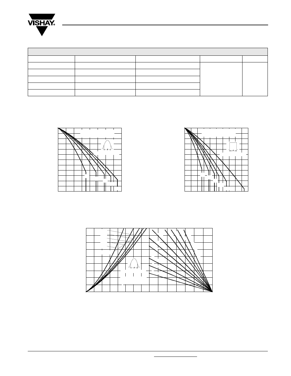
Note
• The table above shows the increment of thermal resistance R
thJC
when devices operate at different conduction angles than DC
Fig. 1 - Current Ratings Characteristics
Fig. 2 - Current Ratings Characteristics
Fig. 3 - Forward Power Loss Characteristics
ΔR
thJC
CONDUCTION
CONDUCTION ANGLE
SINUSOIDAL CONDUCTION
RECTANGULAR CONDUCTION
TEST CONDITIONS
UNITS
180°
0.031
0.023
T
J
= T
J
maximum
K/W
120°
0.038
0.040
90°
0.048
0.053
60°
0.071
0.075
30°
0.120
0.121
140
150
160
170
180
190
200
0
20
40
60
80
100 120 140 160
30°
60°
90°
120°
180°
M
a
x
imu
m
A
llo
w
a
b
le
C
a
se
T
e
mp
e
ra
tu
re
(
°C
)
Cond uction Angle
Average Forward Current (A)
45L...,150... Series
R (DC) = 0.25 K/ W
thJC
140
150
160
170
180
190
200
0
50
100
150
200
250
DC
30°
60°
90°
120°
180°
Ma
x
imu
m
A
llo
w
a
b
le
C
a
se
T
e
m
p
e
ra
tu
re
(
°C
)
Cond uction Period
Average Forward Current (A)
45L..., 150... Series
R (DC) = 0.25 K/ W
thJC
25
50
75
100
125
150
175
200
Maximum Allowa ble Ambient Temperature (°C)
R
=
0
.1
K
/W
-
D
e
lta
R
0.
2
K
/W
0.
6
K/
W
0.8
K/W
1.5
K/ W
2 K/
W
3 K/ W
1
K/W
0
.4
K/
W
0
.3
K
/W
th
SA
160
0
20
40
60
80
100
120
140
160
180
0
40
80
120
RMS Limit
180°
120°
90°
60°
30°
Conduction Angle
Ma
x
imu
m A
v
e
ra
g
e
F
o
rw
a
rd
P
o
w
e
r
L
o
ss
(
W
)
Average Forward Current (A)
45L..., 150... Series
T = 200°C
J