20ets12pbf safe, Series – C&H Technology 20ETS12PbF SAFEIR Series User Manual
Page 4
20ETS12PbF SAFE
IR
Series
Bulletin I2192 12/04
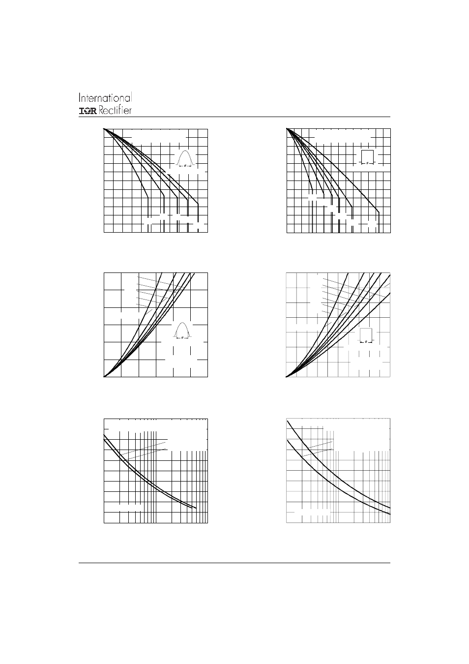
Fig. 1 - Current Rating Characteristics
Fig. 2 - Current Rating Characteristics
Fig. 4 - Forward Power Loss Characteristics
Fig. 3 - Forward Power Loss Characteristics
90
100
110
120
130
140
150
0
2
4
6
8 10 12 14 16 18 20 22
30°
60° 90° 120°
180°
M
a
xi
mu
m
A
llow
ab
le
C
as
e
T
e
mp
er
a
tur
e
(°
C
)
Conduction Angle
Average Forward Current (A)
20ETS.. Series
R (DC) = 1.3 °C/W
thJC
90
100
110
120
130
140
150
0
5
10
15
20
25
30
35
DC
30°
60°
90°
120°
180°
M
ax
im
u
m
A
llo
wa
bl
e C
as
e
T
e
m
pe
rat
u
re (
°C
)
Conduction Period
Average Forward Current (A)
20ETS.. Series
R (DC) = 1.3 °C/ W
thJC
0
5
10
15
20
25
30
0
4
8
12
16
20
24
RMS Limit
180°
120°
90°
60°
30°
Conduction Angle
M
a
xi
m
u
m
A
ver
ag
e F
or
w
a
rd
P
ower
L
o
ss
(
W
)
Average Forward Current (A)
20ETS.. Series
T = 150°C
J
0
5
10
15
20
25
30
35
0
5
10
15
20
25
DC
180°
120°
90°
60°
30°
Average Forward Current (A)
RMS Limit
M
ax
im
um
A
ve
rag
e
Fo
rw
a
rd
P
ow
e
r L
o
ss
(
W
)
Cond uction Period
20ETS.. Series
T = 150°C
J
Fig. 5 - Maximum Non-Repetitive Surge Current
Fig. 6 - Maximum Non-Repetitive Surge Current
50
100
150
200
250
300
1
10
100
Number Of Equal Amplitude Half Cyc le Current Pulses (N)
P
e
ak
H
al
f S
in
e
W
av
e F
or
w
a
rd C
u
rr
e
n
t (
A
)
Initial T = 150°C
@ 60 Hz 0.0083 s
@ 50 Hz 0.0100 s
J
At Any Rated Load Condition And With
Rated V Applied Following Surge.
RRM
20ETS.. Series
50
100
150
200
250
300
0.01
0.1
1
Pulse Train Duration (s)
Maximum Non Repetitive Surge Current
P
eak
H
a
lf S
ine
W
a
ve
F
o
rw
a
rd
Cu
rr
e
n
t (
A
)
Initial T = 150°C
No Voltage Reapplied
Rated V Reapplied
J
RRM
Versus Pulse Train Duration.
20ETS.. Series
Document Number: 94341
www.vishay.com
3