Vishay bccomponents – C&H Technology 057 PSM-SI User Manual
Page 4
Document Number: 28340
For technical questions, contact: [email protected]
www.vishay.com
Revision: 18-Aug-08
3
056/057 PSM-SI
Aluminum Capacitors
Power Standard Miniature Snap-In
Vishay BCcomponents
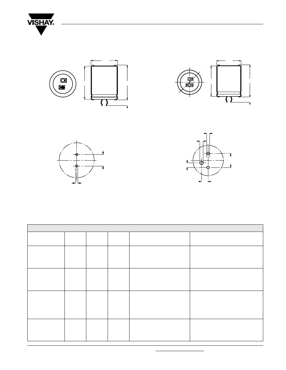
DIMENSIONS in millimeters AND AVAILABLE FORMS
TWO TERMINALS SNAP-IN
THREE TERMINAL SNAP-IN
Table 1
+ TERMINAL
- TERMINAL
Ø D
L + 2 max.
L
Bottom view
5.8 mm
+ 0
- 1
Fig.2 Two terminal snap-in
The minus terminal can be marked with a black dot or with an
imprinted ‘-’ sign.
10 ± 0.1
Ø 2 ± 0.1 (2 x)
Fig.3 Mounting hole diagram
+ TERMINAL
- TERMINAL
L ± 2 max.
L
Bottom view
minus pole
marking
4 ± 0.5
Ø D
Fig.4 Three terminal snap-in
The negative terminal has TWO pins which are BOTH
electrically connected.
Ø 2 ± 0.1 (2 x)
Ø 2.5 ± 0.1
3.3 ± 0.1
10 ± 0.1
4.75 ± 0.1
The 10 mm spacing of the 2 pin snap-in is used as the base
layout and a third hole is added.
The third hole is closer to the negative primary hole so that
polarization is always maintained, together with added
mechanical stability.
Fig.5 Mounting hole diagram
DIMENSIONS in millimeters, MASS AND PACKAGING QUANTITIES
NOMINAL
CASE SIZE
Ø D x L
Ø
D
max.
L
max.
MASS
(g)
PACKAGING QUANTITIES
(units per box)
CARDBOARD BOX DIMENSIONS
L x W x H
(mm)
22 x 25
23
27
≈ 12
100
260 x 250 x 39
22 x 30
23
32
≈ 16
100
260 x 250 x 44
22 x 35
23
37
≈ 20
100
260 x 250 x 49
22 x 40
23
42
≈ 23
100
260 x 250 x 54
25 x 30
26
32
≈ 22
100
290 x 280 x 44
25 x 35
26
37
≈ 24
100
290 x 280 x 49
25 x 40
26
42
≈ 27
100
290 x 280 x 54
25 x 50
26
52
≈ 38
100
290 x 280 x 64
30 x 30
31
32
≈ 30
100
340 x 330 x 44
30 x 35
31
37
≈ 35
100
340 x 330 x 49
30 x 40
31
42
≈ 40
100
340 x 330 x 54
30 x 45
31
47
≈ 45
100
340 x 330 x 59
30 x 50
31
52
≈ 50
100
340 x 330 x 64
35 x 35
36
37
≈ 48
50
390 x 198 x 49
35 x 40
36
42
≈ 55
50
390 x 198 x 54
35 x 45
36
47
≈ 63
50
390 x 198 x 59
35 x 50
36
52
≈ 72
50
390 x 198 x 64