C&H Technology PM25RLA120 User Manual
Page 3
PM25RLA120
Intellimod™ L-Series
Three Phase IGBT Inverter + Brake
25 Amperes/1200 Volts
2
Powerex, Inc., 200 E. Hillis Street, Youngwood, Pennsylvania 15697-1800 (724) 925-7272
Absolute Maximum Ratings, T
j
= 25°C unless otherwise specified
Characteristics
Symbol
PM25RLA120
Units
Power Device Junction Temperature
T
j
-20 to 150
°C
Storage Temperature
T
stg
-40 to 125
°C
Mounting Torque, M5 Mounting Screws
—
31
in-lb
Mounting Torque, M5 Main Terminal Screws
—
31
in-lb
Module Weight (Typical)
—
380
Grams
Supply Voltage, Surge (Applied between P - N)
V
CC(surge)
1000
Volts
Self-protection Supply Voltage Limit (Short Circuit protection Capability)*
V
CC(prot.)
800
Volts
Isolation Voltage, AC 1 minute, 60Hz Sinusoidal
V
ISO
2500
Volts
*VD = 13.5 ~ 16.5V, Inverter Part, Tj = 125°C
IGBT Inverter Sector
Collector-Emitter Voltage (V
D
= 15V, V
CIN
= 15V)
V
CES
1200
Volts
Collector Current (T
C
= 25°C)
±I
C
25
Amperes
Peak Collector Current (T
C
= 25°C)
±I
CP
50
Amperes
Collector Dissipation (T
C
= 25°C)
P
C
116
Watts
IGBT Brake Sector
Collector-Emitter Voltage (V
D
= 15V, V
CIN
= 15V)
V
CES
1200
Volts
Collector Current (T
C
= 25°C)
±I
C
15
Amperes
Peak Collector Current (T
C
= 25°C)
±I
CP
30
Amperes
Collector Dissipation (T
C
= 25°C)
P
C
100
Watts
Diode Rated DC Reverse Voltage (T
C
= 25°C)
V
R(DC)
1200
Volts
Diode Forward Current
I
F
15
Amperes
Control Sector
Supply Voltage (Applied between V
UP1
-V
UPC
, V
VP1
-V
VPC
, V
WP1
-V
WPC
, V
N1
-V
NC
)
V
D
20
Volts
Input Voltage (Applied between U
P
-V
UPC
, V
P
-V
VPC
, W
P
-V
WPC
, U
N
- V
N
- W
N
-Br-V
NC
)
V
CIN
20
Volts
Fault Output Supply Voltage
V
FO
20
Volts
(Applied between U
FO
-V
UPC
, V
FO
-V
VPC
, W
FO
-V
WPC
, F
O
-V
NC
)
Fault Output Current (U
FO
, V
FO
, W
FO
, F
O
Terminals)
I
FO
20
mA
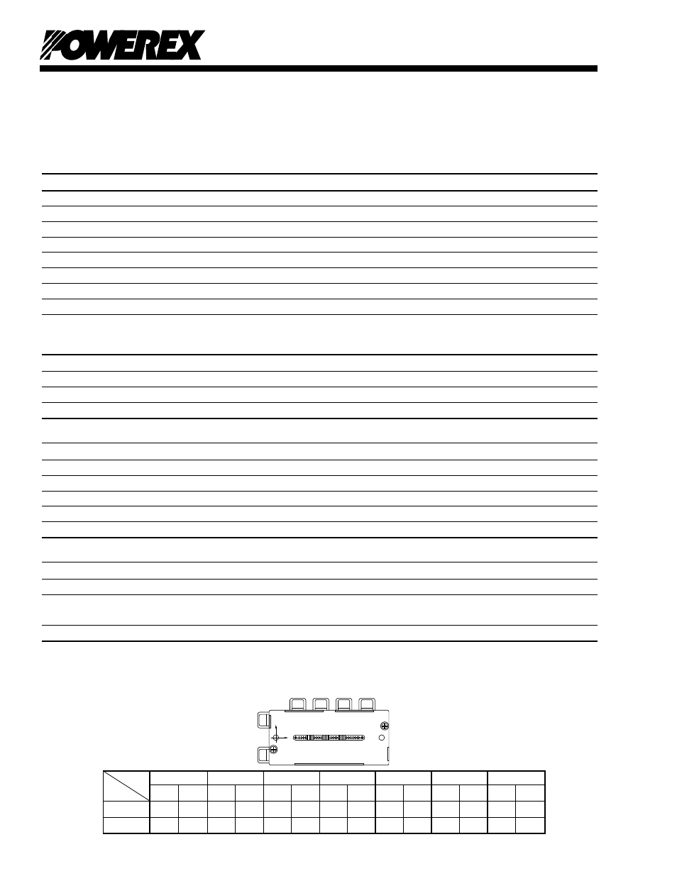
Arm
UP
VP
WP
UN
VN
WN
Br
Axis
IGBT FWDi IGBT FWDi IGBT FWDi IGBT FWDi IGBT FWDi IGBT FWDi IGBT FWDi
X
29.0 29.3 64.0 65.5 85.6 85.9 37.8 37.5 55.2 55.7 75.8 75.3 19.0 22.3
Y
-7.1
1.5
-7.1
2.0
-7.1
2.0
5.1
-4.5
5.1
-4.5
5.1
-4.5 -7.3
6.6
T
C
(Base Plate) Measurement Point
Y
BOTTOM VIEW
X