Vsk.41, .56..pbf series, Vishay high power products, Thyristor/diode and thyristor/thyristor (add-a-pak – C&H Technology VSK.56..PbF Series User Manual
Page 10
Document Number: 94419
For technical questions, contact: [email protected]
www.vishay.com
Revision: 23-Apr-08
9
VSK.41, .56..PbF Series
Thyristor/Diode and Thyristor/Thyristor
(ADD-A-PAK
TM
Generation 5 Power Modules),
45/60 A
Vishay High Power Products
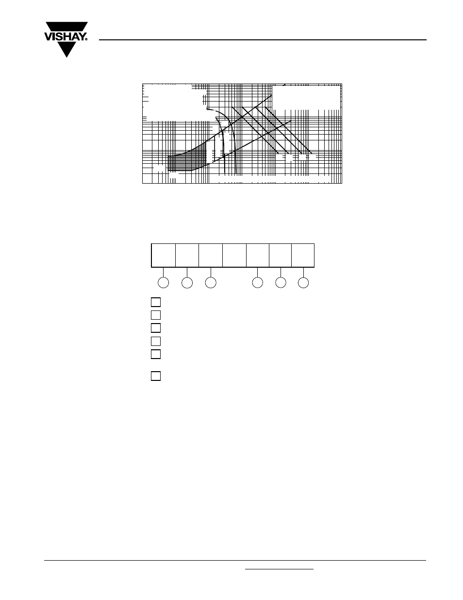
Fig. 24 - Gate Characteristics
ORDERING INFORMATION TABLE
Note
• To order the optional hardware go to www.vishay.com/doc?95172
0.1
1
10
100
0.001
0.01
0.1
1
10
100
1000
(b)
(a)
Rec tangular gate pulse
(4) (3)
(2) (1)
(1) PGM = 100 W, tp = 500 µs
(2) PGM = 50 W, t p = 1 ms
(3) PGM = 20 W, t p = 25 ms
(4) PGM = 10 W, t p = 5 ms
Instantaneous Gate Current (A)
In
st
an
ta
n
e
o
u
s G
a
te
V
o
lt
ag
e
(
V
)
TJ
=
-
4
0
°
C
TJ
=
2
5
°
C
TJ
=
12
5
°C
a)Recommended load line for
b)Rec ommended load line for
VGD
IGD
Frequenc y Limited by PG(AV)
rated di/ dt: 20 V, 30 ohms
tr = 0.5 µs, tp >= 6 µs
<= 30% rated di/ dt: 20 V, 65 ohms
tr = 1 µs, tp >= 6 µs
VSK.41../ .56.. Series
1
-
Module type
2
-
Circuit configuration (see end of datasheet)
3
-
Current code
(1)
4
-
Voltage code (see Voltage Ratings table)
6
-
P = Lead (Pb)-free
5
-
dV/dt code: S90 = dV/dt 1000 V/µs
No letter = dV/dt 500 V/µs
(1)
Available with no auxiliary cathode
(for details see dimensions - link at the end of datasheet)
To specify change: 41 to 42
56 to 57
e.g.:
VSKT57/16P
etc.
Device code
5
1
3
2
4
6
VSK
T
56
/
16
S90
P