Vishay sfernice, Enamelled wirewound power rsistors axial leads – C&H Technology RWM User Manual
Page 3
RWM
Enamelled Wirewound Power Rsistors
Axial Leads
Vishay Sfernice
Document Number: 50008
For technical questions, contact: [email protected]
www.vishay.com
Revision: 11-Dec-06
39
OVERLOAD
Heavy overloads can be endured in the form of short pulses < 0.1 s. Particular requirements should be submitted to Vishay
Sfernice, specifying peak voltage, cycle and environmental conditions.
RECOMMENDATIONS FOR USE
Since these components are high dissipation power resistors, customers are advised to use a high melting point solder.
For low ohmic values, the measurement becomes critical and the connecting wires resistance is to be included. The value is
measured at 5 mm from the resistor body.
Group Mounting
In a still atmosphere, a distance between axes equal to five times the resistor’s diameter is recommended.
Cabinet Mounting
• Unventilated box: dissipation should be reduced (see dimensional drawing).
• Forced ventilation: if conditions are appropriate, dissipation may be doubled or even trebled.
• In any case: the surface temperature at the hottest point should not exceed 450 °C.
These aspects should be considered by the end user.
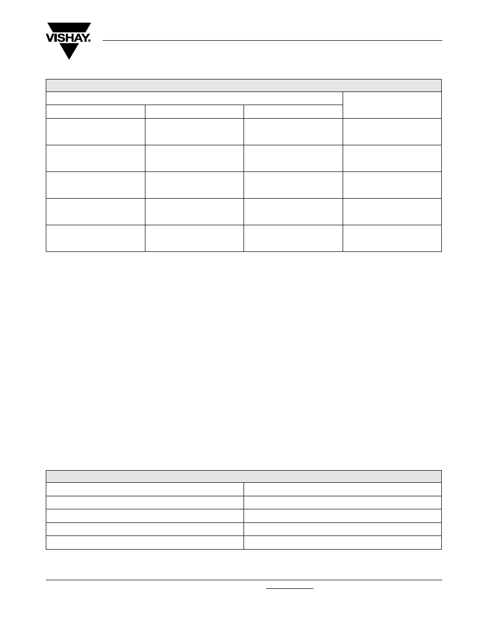
PERFORMANCE
CECC 40201 - EN 140-201
TYPICAL DRIFTS
TESTS
CONDITIONS
REQUIREMENTS
Short Time Overload
10 Pr during 10 s
25 °C ambient
± (2 %
+ 0.1
Ω)
± (0.5 %
+ 0.05
Ω)
Temperature Cycling
- 55 °C + 200 °C
± (1 %
+ 0.05
Ω)
± (0.5 %
+ 0.05
Ω)
Humidity (Steady State)
56 days
40 °C Ambient - R.H. 95 %
± (5 %
+ 0.1
Ω)
± (0.5 %
+ 0.05
Ω)
Terminal Strength
Tensile test: 20 N
2 successive bending
2 full rotations of 180°
± (1 %
+ 0.05
Ω)
± (0.1 %
+ 0.05
Ω)
Load Life
1000 h at Pr
90/30 Cycle
25 °C ambient
± (5 %
+ 0.1
Ω)
± (1.5 %
+ 0.05
Ω)
ELECTRICAL SPECIFICATIONS
Tolerance Standard
± 5 %
On request
± 1 % to ± 10 %
Temperature Coefficient + 75 ppm/°C typical
Dielectric Withstanding Voltage NF EN 140000
500 VRMS - 1 minute - 10 mA
Inductance
non inductive (Ayrton-Perry) winding available