Electrical and mechanical characteristics, t, 25°c unless otherwise specified, Control sector – C&H Technology PM75CLB060 User Manual
Page 4: Thermal characteristics, Recommended conditions for use
PM75CLB060
Intellimod™ L-Series
Three Phase IGBT Inverter
75 Amperes/600 Volts
2
Powerex, Inc., 200 E. Hillis Street, Youngwood, Pennsylvania 15697-1800 (724) 925-7272
3
PM75CLB060
Intellimod™ L-Series
Three Phase IGBT Inverter
75 Amperes/600 Volts
Powerex, Inc., 200 E. Hillis Street, Youngwood, Pennsylvania 15697-1800 (724) 925-7272
Electrical and Mechanical Characteristics, T
j
= 25°C unless otherwise specified
Characteristics Symbol Test Conditions Min. Typ. Max. Units
Control Sector
Short Circuit Trip Level SC -20°C ≤ T
j
≤ 125°C, V
D
= 15V 150 — — Amperes
Short Circuit Current Delay Time t
off(SC)
V
D
= 15V 100 — — µs
Over Temperature Protection OT Trip Level 135 145 155 °C
(Detect T
j
of IGBT Chip) OT
R
Reset Level — 125 — °C
Supply Circuit Under-voltage Protection UV Trip Level 11.5 12.0 12.5 Volts
(-20 ≤ T
j
≤ 125°C) UV
R
Reset Level — 12.5 — Volts
Circuit Current I
D
V
D
= 15V, V
CIN
= 15V, V
N1
-V
NC
— 20 30 mA
V
D
= 15V, V
CIN
= 15V, V
XP1
-V
XPC
— 5 10 mA
Input ON Threshold Voltage V
th(on)
Applied between U
P
-V
UPC
, 1.2 1.5 1.8 Volts
Input OFF Threshold Voltage V
th(off)
V
P
-V
VPC
, W
P
-V
WPC
, U
N
- V
N
- W
N
-V
NC
1.7 2.0 2.3 Volts
Fault Output Current* I
FO(H)
V
D
= 15V, V
CIN
= 15V — — 0.01 mA
I
FO(L)
V
D
= 15V, V
CIN
= 15V — 10 15 mA
Fault Output Pulse Width* t
FO
V
D
= 15V 1.0 1.8 — ms
*Fault output is given only when the internal SC, OT and UV protections schemes of either upper or lower devide operate to protect it.
Thermal Characteristics
Characteristic Symbol Condition Min. Typ. Max. Units
Junction to Case Thermal Resistance R
th(j-c)Q
IGBT (Per 1/6 Module) (Note 1) — — 0.42 °C/Watt
R
th(j-c)D
FWDi (Per 1/6 Module)(Note 1) — — 0.69 °C/Watt
R
th(j-c)Q
IGBT (Per 1/6 Module) (Note 2) — — 0.32** °C/Watt
R
th(j-c)D
FWDi (Per 1/6 Module)(Note 2) — — 0.53** °C/Watt
Contact Thermal Resistance R
th(c-f)
Case to Fin Per Module, — — 0.038 °C/Watt
Thermal Grease Applied (Note 1)
** If you use this value, R
th(f-a)
should be measured just under the chips.
Recommended Conditions for Use
Characteristic Symbol Condition Value Units
Supply Voltage V
CC
Applied across P-N Terminals ≤400 Volts
Control Supply Voltage*** V
D
Applied between V
UP1
-V
UPC
, 15.0 ± 1.5 Volts
V
VP1
-V
VPC
, V
WP1
-V
WPC
,
V
N1
-V
NC
Input ON Voltage V
CIN(on)
Applied between U
P
-V
UPC
, ≤0.8 Volts
Input OFF Voltage V
CIN(off)
V
P
-V
VPC
, W
P
-V
WPC
, U
N
- V
N
- W
N
-V
NC
≥9.0 Volts
PWM Input Frequency f
PWM
≤20 kHz
Arm Shoot-through Blocking Time t
DEAD
Input Signal ≥2.0 µs
*** With ripple satisfying the following conditions: dv/dt swing ≤ ±5V/µs, Variation ≤ 2V peak to peak.
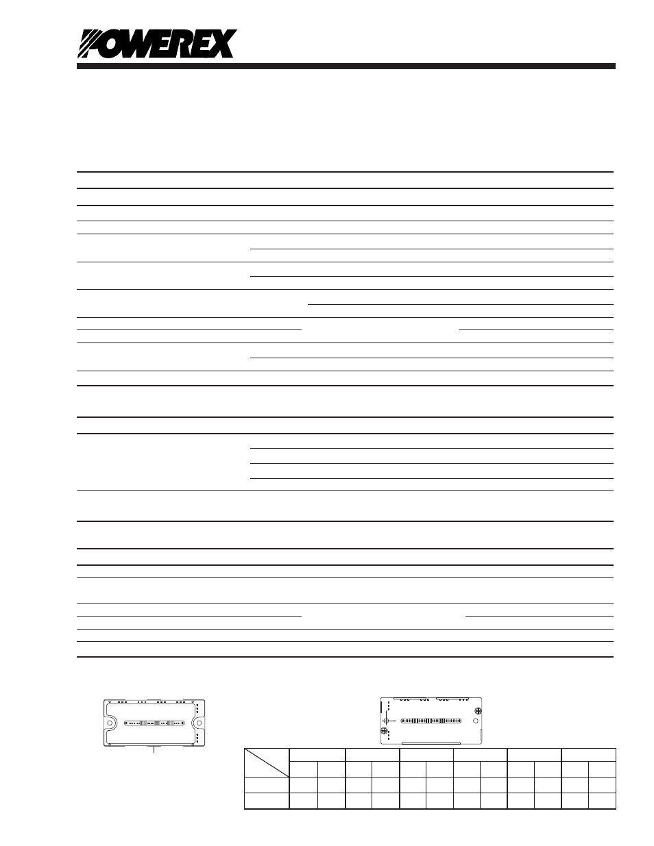
Arm UP VP WP UN VN WN
Axis IGBT FWDi IGBT FWDi IGBT FWDi IGBT FWDi IGBT FWDi IGBT FWDi
X
28.7 28.7 65.2 65.2 85.3 85.3 38.0 38.0 55.4 55.4 75.5 75.5
Y -6.6 0.85 -6.6 2.5 -6.6 2.5 4.6 -4.5 4.6 -4.5 4.6 -4.5
Note 2: T
C
(under the chip) Measurement Point
Note 1:T
C
(base plate) Measurement Point
Y
X
BOTTOM VIEW
TOP VIEW
TC
MEASUREMENT
POINT