Nd41, Pow-r-blok – C&H Technology ND41__26 User Manual
Page 5
Powerex, Inc., 173 Pavilion Lane, Youngwood, Pennsylvania 15697 (724) 925-7272
POW-R-BLOK
TM
www.pwrx.com
Dual Diode Isolated Module
260 Amperes / Up to 2400 Volts
Revision Date: 05/17/2010
ND41__26
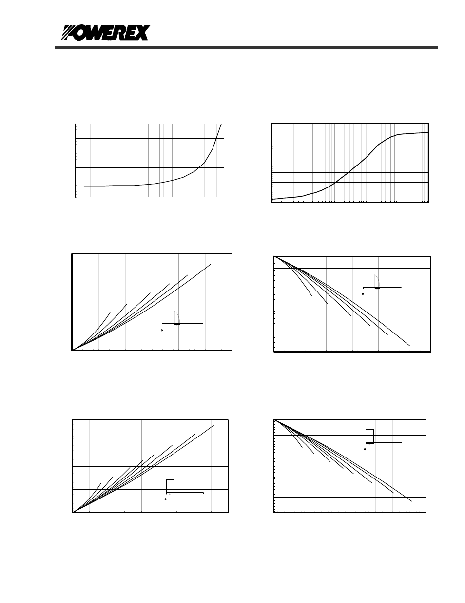
M aximum Transient Thermal Impedance
.00
.02
.04
.06
.08
.10
.12
.14
.16
0.001
0.01
0.1
1
10
100
Time - t - Seconds
Thermal
Im
pedance -
Rj
c -
°C/
W
(Junction to Case)
Ma x im um On-Sta te Forw a rd Volta ge Drop
0
1
2
3
4
5
10
100
1000
10000
Instantaneous On-State Current - Ifm - Am peres
O
n-S
ta
te
V
ol
ta
ge
- V
fm - V
ol
ts
( Tj = 150 °C )
0
180
360
CONDUCTION ANGLE
Maximum On-State Power Dissipation
15°
30°
60°
90°
120°
180°
0
50
100
150
200
250
300
0
50
100
150
200
250
300
Average On-State Current - If(av) - Amperes
Max. P
ower D
issipation P
er D
iode - W
atts_
(Sinusoidal Waveform )
0
180
360
CONDUCTION ANGLE
Maximum Allowable Case Temperature
120°
90°
60°
30°
15°
180°
110
115
120
125
130
135
140
145
150
0
50
100
150
200
250
300
Average On-State Current - If(av) - Amperes
M
ax. Case Temperature - Tcase -°C_
(Sinusoidal Waveform)
0
180
360
CONDUCTION ANGLE
Maximum On-State Power Dissipation
90°
60°
30°
120°
180°
270°
15°
360°
0
50
100
150
200
250
300
350
400
0
50
100
150
200
250
300
350
400
450
Average On-State Current - If(av) - Amperes
M
ax
. Pow
er
Dis
si
pa
tion Pe
r Diode
- W
atts
_
(Rectangular Waveform)
0
180
360
CONDUCTION ANGLE
Maximum Allowable Case Temperature
270°
180°
120°
90°
60°
30°
15°
360°C
90
100
110
120
130
140
150
0
50
100
150
200
250
300
350
400
450
Average On-State Current - If(av) - Amperes
Max. Case Temperature - Tcase -°C
_
(Rectangular Waveform)