St180cpbf series, Vishay high power products – C&H Technology ST180CPbF Series User Manual
Page 6
Document Number: 94396
For technical questions, contact: [email protected]
www.vishay.com
Revision: 30-Apr-08
5
ST180CPbF Series
Phase Control Thyristors
(Hockey PUK Version), 350 A
Vishay High Power Products
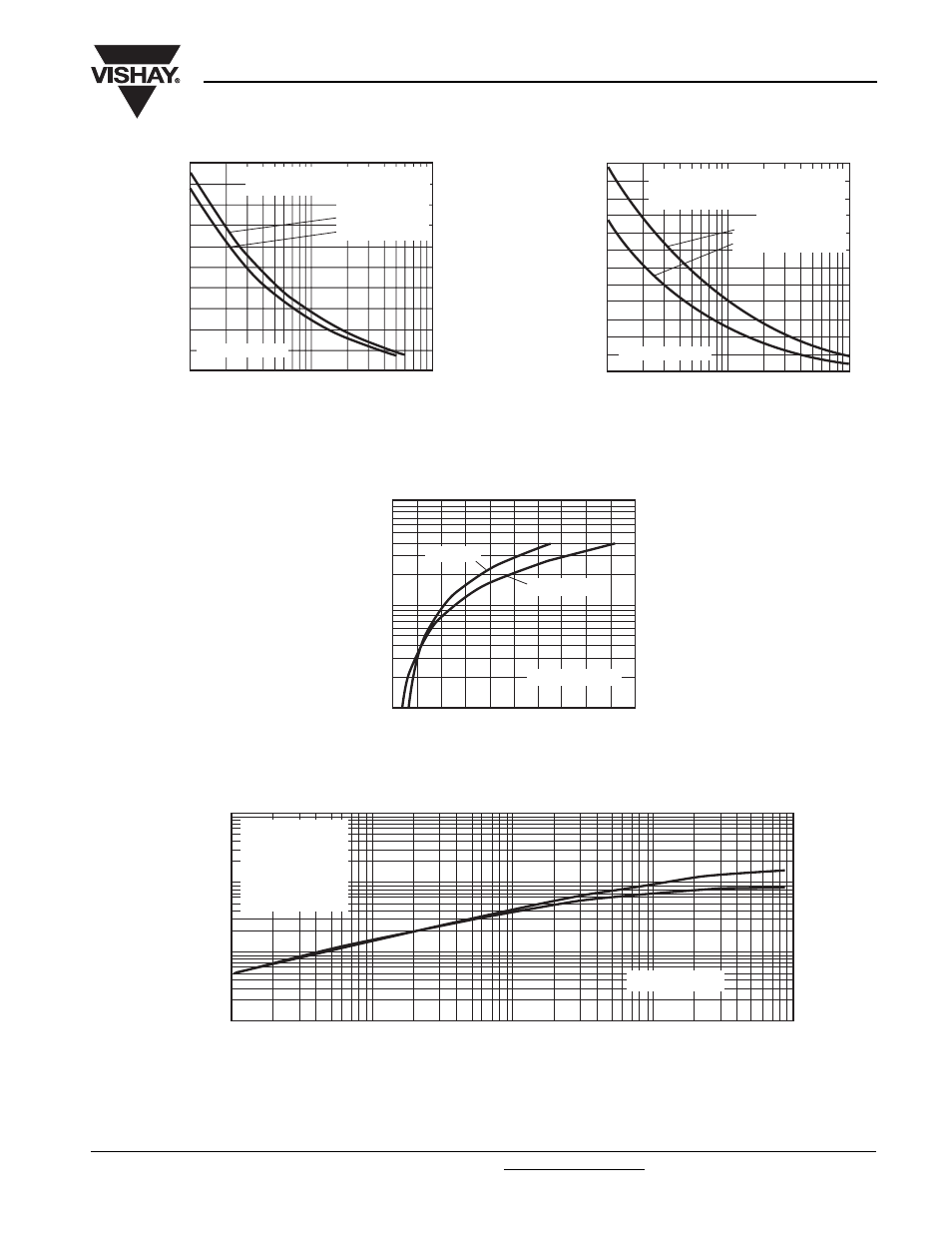
Fig. 7 - Maximum Non-Repetitive Surge Current
Single and Double Side Cooled
Fig. 8 - Maximum Non-Repetitive Surge Current
Single and Double Side Cooled
Fig. 9 - On-State Voltage Drop Characteristics
Fig. 10 - Thermal Impedance Z
thJ-hs
Characteristics
2000
1
10
100
2500
3500
4000
Number of Equal Amplitude Half Cycle
Current Pulses (N)
Peak Half Sine Wave
On-State Current (A)
4500
3000
At any rated load condition and with
rated V
RRM
applied following surge
ST180C..C Series
Initial T
J
= 125 °C
at 60 Hz 0.0083 s
at 50 Hz 0.0100 s
0.01
0.1
1
Pulse Train Duration (s)
Peak Half Sine Wave
On-State Current (A)
2000
2500
3500
4000
4500
5000
3000
No Voltage Reapplied
Rated V
RRM
Reapplied
Maximum non repetitive surge current
versus pulse train duration. Control of
conduction may not be maintained.
Initial T
J
= 125 °C
ST180C..C Series
100
1
2
3
4
5
6
1000
10 000
Instantaneous On-State Current (A)
Instantaneous On-State Voltage (V)
T
J
= 25 °C
T
J
= 125 °C
ST180C..C Series
0.001
0.01
0.1
1
0.001
Square Wave Pulse Duration (s)
Z
thJ-hs
- Transient
Thermal Impedance (K/W)
0.01
0.1
1
10
Steady state value
R
thJ-hs
= 0.17 K/W
(Single side cooled)
R
thJ-hs
= 0.08 K/W
(Double side cooled)
(DC operation)
ST180C..C Series