Vishay dale, Wirewound resistors, commercial coated, axial lead – C&H Technology CW User Manual
Page 2
CW
Wirewound Resistors, Commercial Coated, Axial Lead
Vishay Dale
Document Number: 30215
For technical questions, contact: [email protected]
www.vishay.com
Revision: 10-Dec-07
21
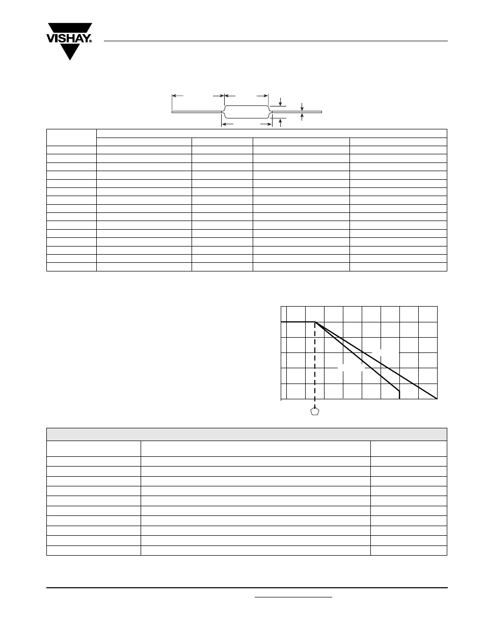
DIMENSIONS in inches [millimeters]
Notes
(1)
On some standard reel pack methods, the leads may be trimmed to a shorter length than shown
(2)
B (maximum) dimension is clean lead to clean lead
MATERIAL SPECIFICATIONS
Element: Copper-nickel alloy or nickel-chrome alloy,
depending on resistance value
Core: Ceramic: Steatite or alumina, depending on physical
size
Coating: Special high temperature silicone
Standard Terminals: Tinned Copperweld
®
End Caps: Stainless steel
Part Marking: DALE, model, wattage
(3)
, value, tolerance,
date code
Note
(3)
Wattage marked on resistor will be “V” characteristic, CW1/2 will
not be marked with wattage
Note
(4)
All
ΔR figures shown are maximum, based upon testing requirements per MIL-PRF-26 at a maximum operating temperature of + 350 °C.
ΔR maximum figures are considerably lower when tested at a maximum operating temperature of + 250 °C.
MODEL
DIMENSIONS in inches [millimeters]
A
B (maximum)
(2)
C
D
CW1/2
0.250 ± 0.031 [6.35 ± 0.787]
0.281 [7.14]
0.085 ± 0.020 [2.16 ± 0.508]
0.020 ± 0.002 [0.508 ± 0.051]
CW001
0.406 ± 0.031 [10.31 ± 0.787]
0.437 [11.10]
0.094 ± 0.031 [2.39 ± 0.787]
0.020 ± 0.002 [0.508 ± 0.051]
CW01M
0.285 ± 0.025 [7.24 ± 0.635]
0.311 [7.90]
0.110 ± 0.015 [2.79 ± 0.381]
0.020 ± 0.002 [0.508 ± 0.051]
CW002
0.625 ± 0.062 [15.87 ± 1.57]
0.765 [19.43]
0.250 ± 0.032 [6.35 ± 0.813]
0.040 ± 0.002 [1.02 ± 0.051]
CW02M
0.500 ± 0.062 [12.70 ± 1.57]
0.562 [14.27]
0.185 ± 0.015 [4.70 ± 0.381]
0.032 ± 0.002 [0.813 ± 0.051]
CW02B
0.562 ± 0.062 [14.27 ± 1.57]
0.622 [15.80]
0.188 ± 0.032 [4.78 ± 0.813]
0.032 ± 0.002 [0.813 ± 0.051]
CW02B...13
0.500 ± 0.062 [12.70 ± 1.57]
0.563 [14.30]
0.188 ± 0.032 [4.78 ± 0.813]
0.032 ± 0.002 [0.813 ± 0.051]
CW02C
0.500 ± 0.062 [12.70 ± 1.57]
0.593 [15.06]
0.218 ± 0.032 [5.54 ± 0.813]
0.040 ± 0.002 [1.02 ± 0.051]
CW02C...14
0.500 ± 0.062 [12.70 ± 1.57]
0.593 [15.06]
0.218 ± 0.032 [5.54 ± 0.813]
0.032 ± 0.002 [0.813 ± 0.051]
CW005
0.875 ± 0.062 [22.22 ± 1.57]
1.0 [25.40]
0.312 ± 0.032 [7.92 ± 0.813]
0.040 ± 0.002 [1.02 ± 0.051]
CW005...2
0.875 ± 0.062 [22.22 ± 1.57]
1.0 [25.40]
0.250 ± 0.032 [6.35 ± 0.813]
0.032 ± 0.002 [0.813 ± 0.051]
CW005...3
0.875 ± 0.062 [22.22 ± 1.57]
1.0 [25.40]
0.312 ± 0.032 [7.92 ± 0.813]
0.032 ± 0.002 [0.813 ± 0.051]
CW007
1.218 ± 0.062 [30.94 ± 1.57]
1.281 [32.54]
0.312 ± 0.032 [7.92 ± 0.813]
0.040 ± 0.002 [1.02 ± 0.051]
CW010
1.781 ± 0.062 [45.24 ± 1.57]
1.875 [47.62]
0.375 ± 0.032 [9.52 ± 0.813]
0.040 ± 0.002 [1.02 ± 0.051]
CW010...3
1.781 ± 0.062 [45.24 ± 1.57]
1.875 [47.62]
0.375 ± 0.032 [9.52 ± 0.813]
0.032 ± 0.002 [0.813 ± 0.051]
D
C
1.50 [38.10]
(1)
minimum
A
B
RATED POWER
IN
%
AMBIENT TEMPERATURE IN °C
25
0
20
40
60
80
100
120
- 65
150
350
50
250
0
- 50
CHAR. U
Derating
CHAR. V
PERFORMANCE
(4)
TEST
CONDITIONS OF TEST
TEST LIMITS
(CHARACTERISTIC V)
Thermal Shock
Rated power applied until thermally stable, then a minimum of 15 min at - 55 °C
± (2.0 % + 0.05
Ω) ΔR
Short Time Overload
5 x rated power (3.75 W and smaller), 10 × rated power (4 W and larger) for 5 s
± (2.0 % + 0.05
Ω) ΔR
Dielectric Withstanding Voltage
1000 V
rms
, 1 min
± (0.1 % + 0.05
Ω) ΔR
Low Temperature Storage
- 65 °C for 24 h
± (2.0 % + 0.05
Ω) ΔR
High Temperature Exposure
250 h at + 350 °C
± (4.0 % + 0.05
Ω) ΔR
Moisture Resistance
MIL-STD-202 Method 106, 7b not applicable
± (2.0 % + 0.05
Ω) ΔR
Shock, Specified Pulse
MIL-STD-202 Method 213, 100 g’s for 6 ms, 10 shocks
± (0.2 % + 0.05
Ω) ΔR
Vibration, High Frequency
Frequency varied 10 to 2000 Hz, 20 g peak, 2 directions 6 h each
± (0.2 % + 0.05
Ω) ΔR
Load Life
2000 h at rated power, + 25 °C, 1.5 h “ON”, 0.5 h “OFF”
± (3.0 % + 0.05
Ω) ΔR
Terminal Strength
5 to 10 s 10 pound pull test; torsion test - 3 alternating directions, 360 °C each
± (1.0 % + 0.05
Ω) ΔR