Rssd, Vishay sfernice – C&H Technology RSSD User Manual
Page 3
RSSD
Adjustable Wirewound Vitreous Resistors
Low Ohmic Values (0.10
Ω available)
Vishay Sfernice
Document Number: 50020
For technical questions, contact: [email protected]
www.vishay.com
Revision: 24-Jan-07
71
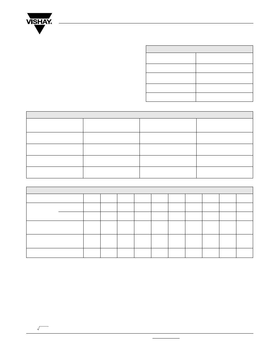
MECHANICAL SPECIFICATIONS
Mechanical Protection
Vishay Sfernice Special cement
Resistive Element
nickel alloy wire
Connections
AN collars
CS supporting collars
Average Unit Weight
10 to 1350 g
ENVIRONMENTAL SPECIFICATIONS
Temperature Limits
- 55 °C + 450 °C
Climatic Category
- 55 °C/+ 200 °C/56 days
ADDITIONAL TAPPINGS
Are supplied with their adjustable collars fastened but not set to any specifi c value. Please note that, on request, all tappings can
be adjusted by VISHAY SFERNICE. For adjustment purposes we would need to be advised of the ohmic values, and tolerances
of the sections in successive order in addition to their sum Rn.
The permissible maximum value for an adjustment should take into account the possible negative tolerance of Rn.
Please consult VISHAY SFERNICE regarding the acceptable tolerance.
RECOMMENDATIONS FOR USE
Maximum Current Strength:
The ohmic value and the power decrease as the connections are brought together. To avoid overload, the maximum current
strength that is permissible for Rn should never be exceeded:
I
max
=
ELECTRICAL SPECIFICATIONS
Resistance Range
0.12
Ω to 560 Ω
(E12 series)
Standard Resistance
R
≥ 10 Ω ± 5 %
Tolerance
1
Ω ≤ R ≤ 10 Ω ± 10 %
0R1
≤ R < 1 Ω ± 20 %
Power Rating
14 W to 600 W at 25 °C
Temperature Coefficient
+ 75 ppm/°C (typical)
PERFORMANCE
TESTS
CONDITIONS
REQUIREMENTS
TYPICAL
VALUES
AND DRIFTS
Short Time Overload
10 Pr during 5 s
2 %
1 %
Climatic Sequence
- 55 °C + 200 °C
5 cycles
3 %
1 %
Thermal Shock
Load at 100 % Pr
followed by cold - 55 °C/15
2 %
or 0.05
Ω
1 %
Load Life
90/30 cycle
1000 h at Pr at + 25 °C
5 %
1.5 %
SPECIAL FEATURES
RSSD TYPE
8 Ч 34
10 Ч 50
13 Ч 70
16 Ч 94
20 Ч 117 25 Ч 138 25 Ч 168 30 Ч 250 40 Ч 370 50 Ч 373
Power Rating
at 25 °C
Continuous
16 W
25 W
42 W
70 W
100 W
140 W
200 W
280 W
450 W
600 W
Reduced
14 W
22 W
38 W
62 W
90 W
125 W
170 W
240 W
360 W
450 W
Resistance Ohmic Range
(E12, E24 Series)
with 1 Tapping
0.12
Ω
10
Ω
0.12
Ω
22
Ω
0.12
Ω
43
Ω
0.33
Ω
75
Ω
0.22
Ω
100
Ω
0.10
Ω
150
Ω
0.12
Ω
220
Ω
0.22
Ω
360
Ω
0.47
Ω
470
Ω
0.68
Ω
560
Ω
Maximum Number
of Additional
Tapping
0
1
1
1
1
1
2
2
4
4
Reduction % of Ohmic
Value by Tapping
23
21
14
11
10
8
6.5
6
5.7
5.7
Pr/Rn