C&H Technology PS51787 User Manual
Page 2
PS51787
Intellimod™ Module
Dual-In-Line Intelligent Power Factor Correction Module
20 Amperes/600 Volts
2
03/10 Rev. 0
Powerex, Inc., 173 Pavilion Lane, Youngwood, Pennsylvania 15697 (724) 925-7272 www.pwrx.com
Absolute Maximum Ratings, T
j
= 25°C unless otherwise specified
Characteristics
Symbol
PS51787
Units
Input Supply Voltage (Between S-R Terminals)
V
i
264
V
rms
Input Supply Voltage, Surge (Between S-R Terminals)
V
i(surge)
500
Volts
Output Voltage (Between P-N Terminals)
V
O
450
Volts
Output Voltage, Surge (Between P-N Terminals)
V
O(surge)
500
Volts
Collector-Emitter Voltage
V
CES
600
Volts
Repetative Peak Reverse Voltage
V
RRM
600
Volts
Input Current, 100% Load (T
C
≤ 100°C, V
i
= 220V
rms
, V
O
= 390V, f
PWM
= 20kHz)
I
i
20
A
rms
Input Current, 125% Load (T
C
≤ 100°C, V
i
= 220V
rms
, V
O
= 390V,
I
i(125%)
25
A
rms
f
PWM
= 20kHz, Non-repetative, within 1 Minute)
I
2
t for Fusing (Value for 1 Cycle of Surge Current, tw = 8.3ms, Non-repetitive)
I
2
t
120
A
2
s
Junction Temperature*
T
j
-20 to 150
°C
Module Case Operation Temperature**
T
C
-20 to 100
°C
Storage Temperature
T
stg
-40 to 125
°C
Mounting Torque, M3 Mounting Screws
—
8.7
in-lb
Module Weight (Typical)
—
21
Grams
Isolation Voltage, AC 1 minute, 60Hz Sinusoidal, Connection Pins to Heatsink Plate
V
ISO
2500
Vrms
Control Sector
Control Supply Voltage (Applied between V
D
-GND)
V
D
20
Volts
Input Voltage (Applied between V
IN
-GND)
V
IN
0 ~ V
D
+0.5
Volts
*The maximum junction temperature rating of the power chips integrated within the DIPPFC is 150°C (@T
C
≤ 100°C). However, to ensure safe operation of the DIPPFC,
the average junction temperature should be limited to T
j(avg)
≤ 125°C (@T
C
≤ 100°C).
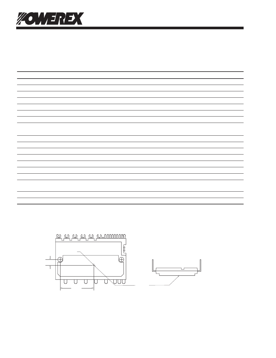
**T
C
Measurement Point
4.6 mm
25.4mm
IGBT
CONTROL TERMINALS
POWER TERMINALS
T
C
POINT